Variable rate pump

a variable rate, pump technology, applied in the direction of piston pumps, positive displacement liquid engines, gearing, etc., can solve the problem that the speed of the input rotational power supply cannot be readily adjusted

Inactive Publication Date: 2003-08-19
CDS JOHN BLUE
View PDF4 Cites 10 Cited by
  • Summary
  • Abstract
  • Description
  • Claims
  • Application Information

AI Technical Summary

Benefits of technology

The secondary drive gear 19' is supported by the outboard gear holder 16 and rotationally fixed to the outboard gear holder 16 with a key 17 for common rotation about the axis A. The outboard gear holder 16 is positioned around a needle cup bearing 12 and inner race 13 which is supported in turn by the thrust holder 10. A second sleeve bearing 18 is positioned between the outboard gear holder 16 and the main driveshaft 46. The bearing 18 allows for free rotational operation of the outboard gear holder 16 with respect to the main driveshaft 46. A thrust bearing composed of raceways 14' and a roller cage 15' is positioned between the outboard gear holder 16 and thrust holder 10 due to the 90 degree positioning of the drive and pinion gears 19, 19', 36 producing a thrust force acting to separate the drive gears 19, 19'. The outboard gear holder 16 contains a bolt pattern to affix a stroke locator 20 through the use of bolts 21 or other suitable device(s). This bolt pattern is offset so as to fix a radially-extending cam slot 20a of the stroke locator 20 with respect to rotational orientation to the secondary drive gear 19'.

Problems solved by technology

While such machines require a linear, oscillating power source for operation, mechanical power sources are typically rotational.
In many situations, the speed of the input rotational power supply cannot be readily adjusted in order to adjust the resulting piston stroke frequency.
Unfortunately, however, when using this conventional system, the machine must be stopped in order to allow an operator to unlock, alter, and relock the eccentrics' relative positions.

Method used


Image

  • Variable rate pump
  • Variable rate pump
  • Variable rate pump

Examples


Embodiment Construction

A detailed description of the elements required for an understanding of the present invention is provided.

Hereinafter the rotational operation of a piston pump driving mechanism 210 according to the present invention will be described.

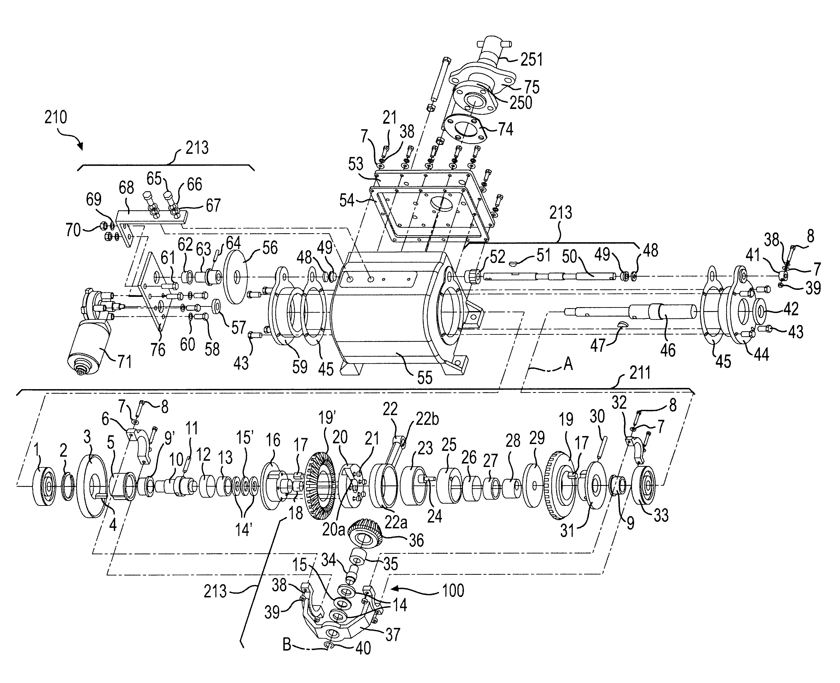
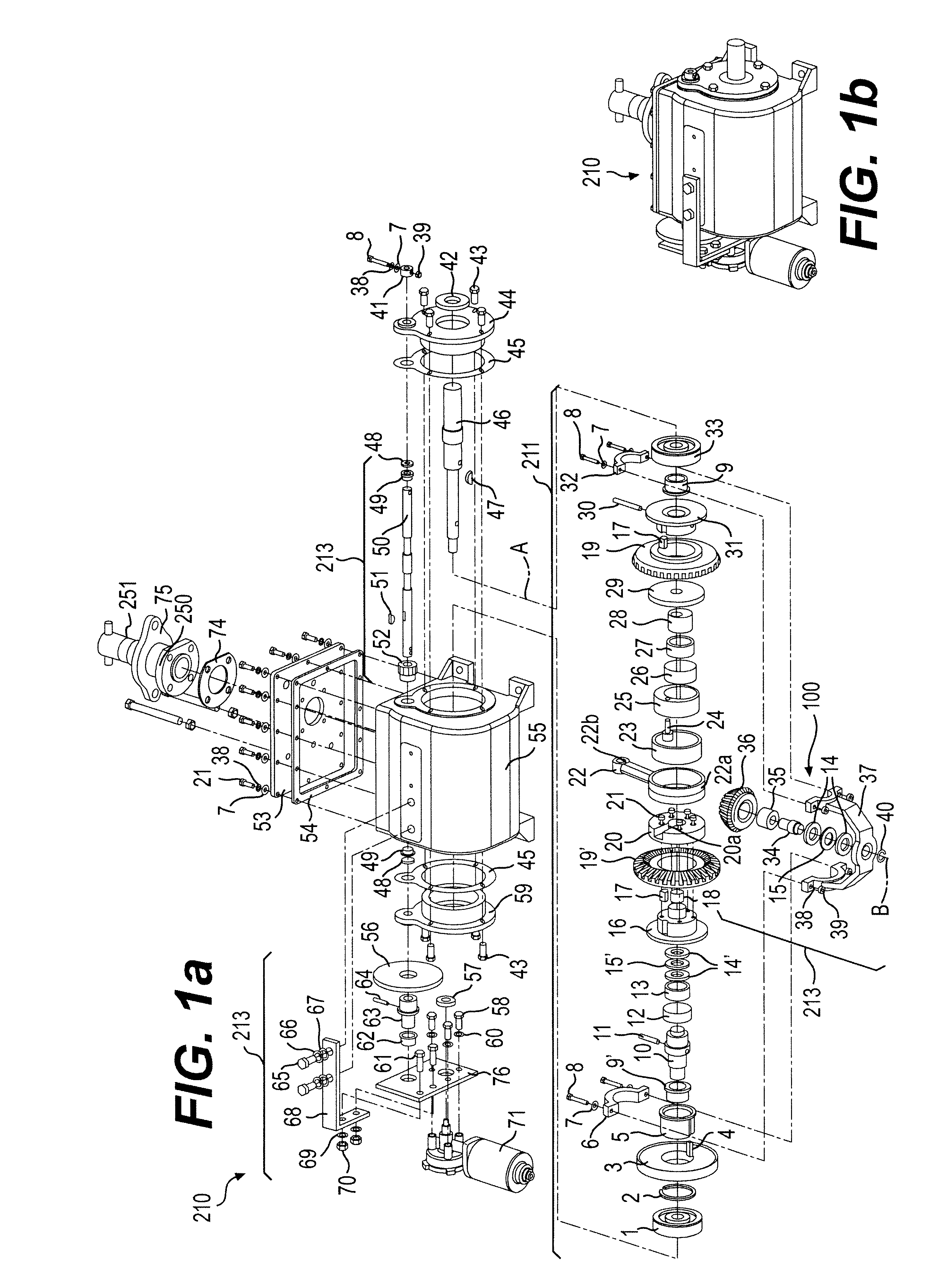
As shown in the exploded view of FIG. 1, the pump 210 includes a connecting rod driving mechanism 211. The connecting rod driving mechanism has a crankcase housing 55 that supports an inboard bearing housing 44 and outboard bearing housing 59. These housings 44, 59 are held in place with bolts 43, or other suitable holding devices. During operation, the crankcase housing 55 contains oil for lubrication and therefore the bearing housings 44, 59 and crankcase housing 55 are sealed together with gaskets 45. A cover plate 53 is also affixed to the crankcase housing 55 through the use of bolts 21, lock washers 38, and flat washers 7 or other suitable devices and sealed with a cover plate gasket 54.

The inboard bearing housing 44 supports an inboard bearing 3...


PUM


Abstract

A rotational power input is converted into a linearly oscillating power output through the use of counter-rotating nested eccentrics. The outer eccentric is connected to an input end of a connecting rod, which is in turn connected at an output end thereof to a piston of a piston pump. The piston is constrained to translational movement along an axis D. Drive gears are rotationally fixed to each of the eccentrics and geared to each other through an intermediate pinion having a rotational axis B. An angular position beta of the pinion axis B relative to the axis D determines the output oscillation stroke length and flow rate of the pump. An actuator is geared to a pinion bracket that holds the pinion. The actuator can be actuated on-the-fly to alter the angle beta and pumping rate of the pump.

Description

1. Field of the InventionThe present invention relates generally to crankcases that convert an input rotary motion into an output linear motion, such as is required for piston pumps, and more specifically to mechanisms that vary the stroke length of such piston pumps.2. Description of Related ArtA variety of machines require a linear, oscillating input motion for operation. For example, positive displacement piston pumps require an linear, oscillating motion to drive their pistons in and out of the piston chamber to displace a control volume within the chamber. Such piston pumps are used in farm machinery such as liquid-fertilizer distribution systems to disperse a controlled volume of liquid fertilizer.While such machines require a linear, oscillating power source for operation, mechanical power sources are typically rotational. For example, motors and engines are typically rotational power sources. In farm machinery, for example, various implements must be powered by a rotational ...

Claims


Application Information

Patent Timeline
Patent Type & Authority Patents(United States)
IPC IPC(8): F01B9/04F01B9/00F04B49/12F04B9/02F04B9/04
CPCF01B9/042F04B9/02F04B49/123F04B9/045Y10T74/1667
Inventor JONES, KENT R.
Owner CDS JOHN BLUE
Why Eureka
Try Eureka