Mounting structure for temperature detecting member in rechargeable battery

US6610439B1Inactive Publication Date: 2003-08-26PANASONIC CORP +1

Image

  • Mounting structure for temperature detecting member in rechargeable battery
  • Mounting structure for temperature detecting member in rechargeable battery
  • Mounting structure for temperature detecting member in rechargeable battery

Examples


Embodiment Construction

Preferred embodiments of a rechargeable battery in accordance with the present invention will be hereinafter described with reference to FIGS. 1 to 4.

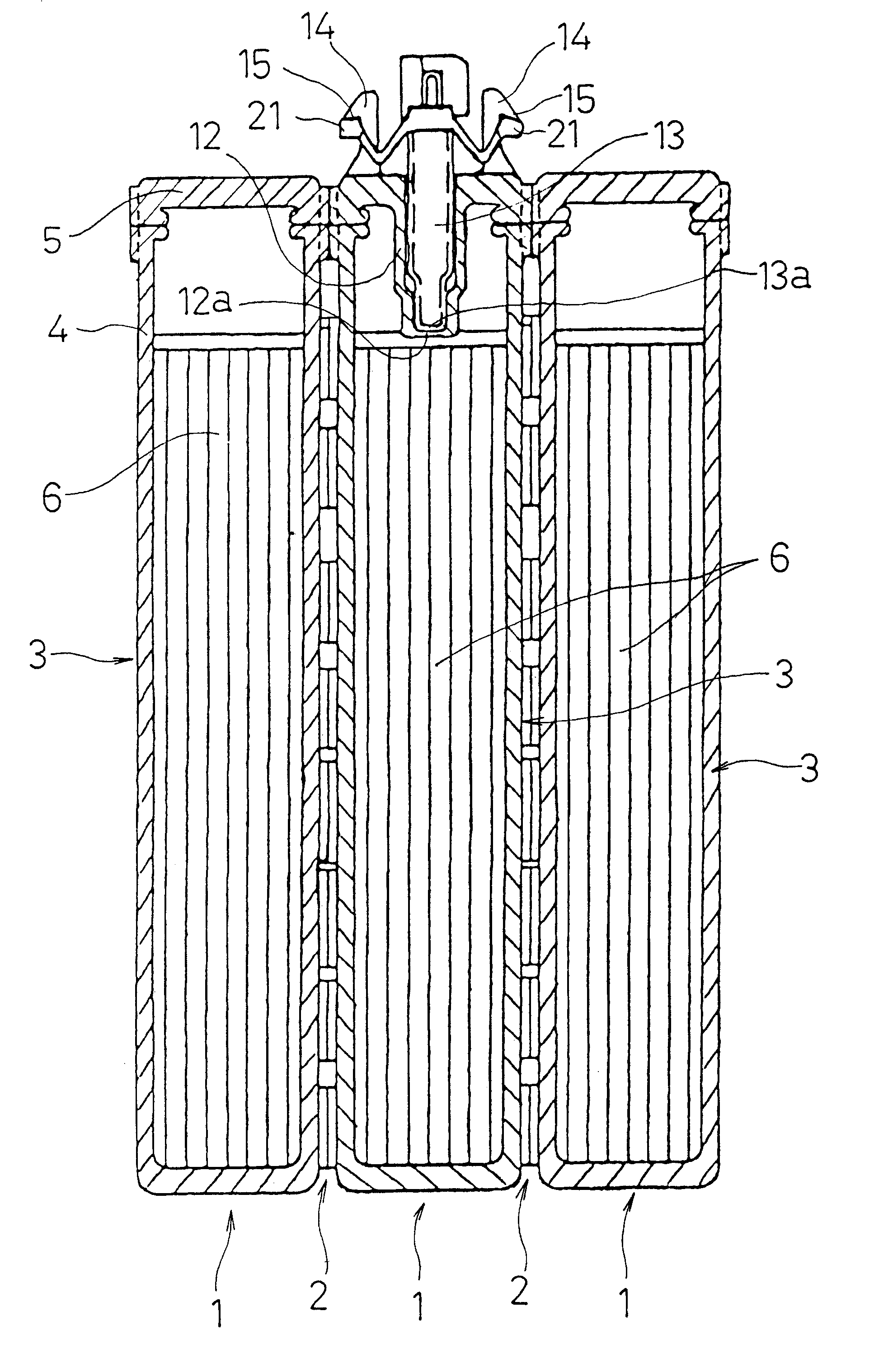
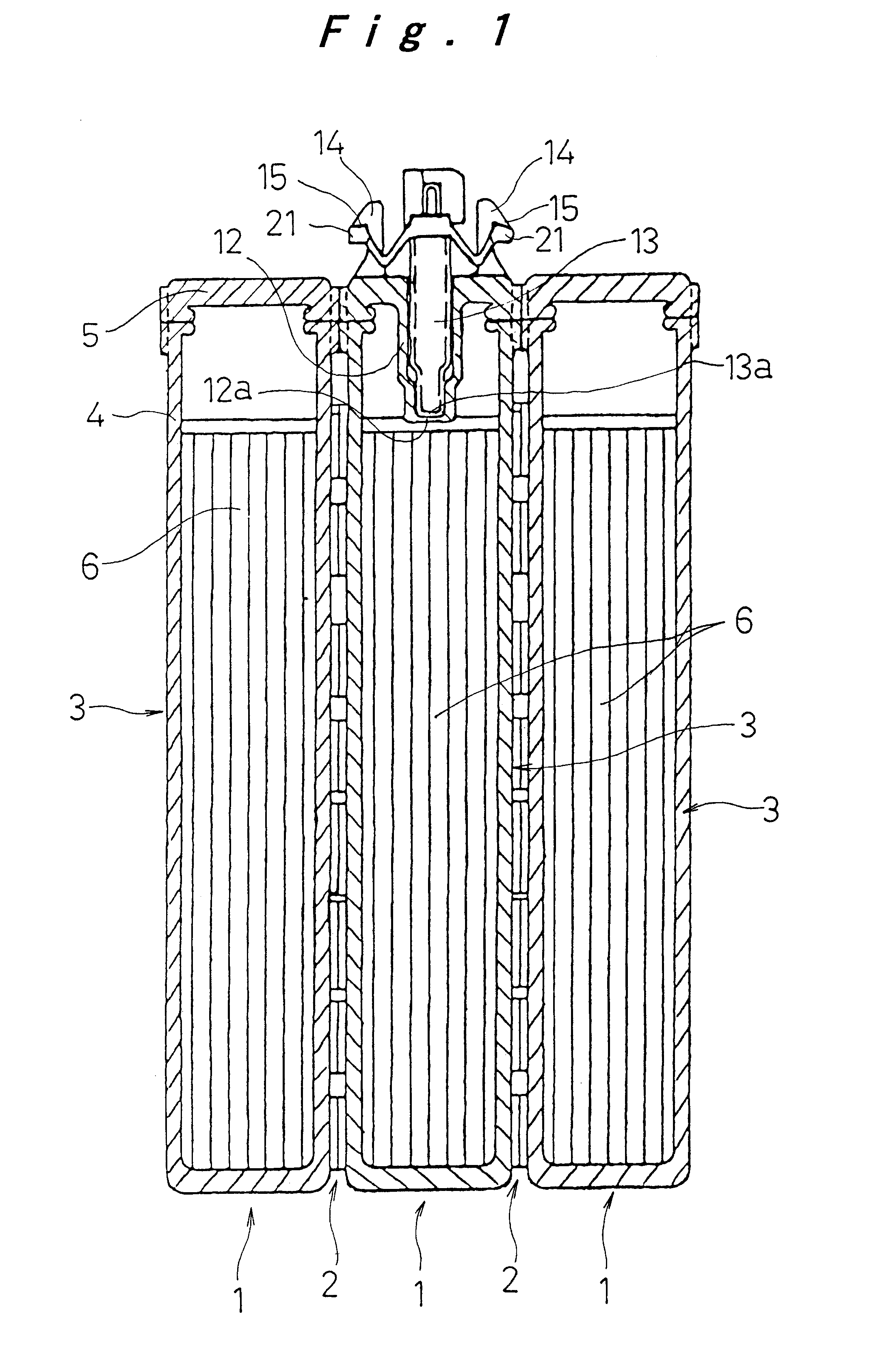
The present invention is applied to a battery pack of nickel metal hydride batteries, which is suitable for use as a drive power source for an electric vehicle. As shown in FIG. 1, a plurality of rechargeable batteries 1 are arranged side by side, and connected electrically in series for use. Coolant passages 2 are formed between opposing walls of adjacent batteries 1 for forcibly cooling the batteries 1.

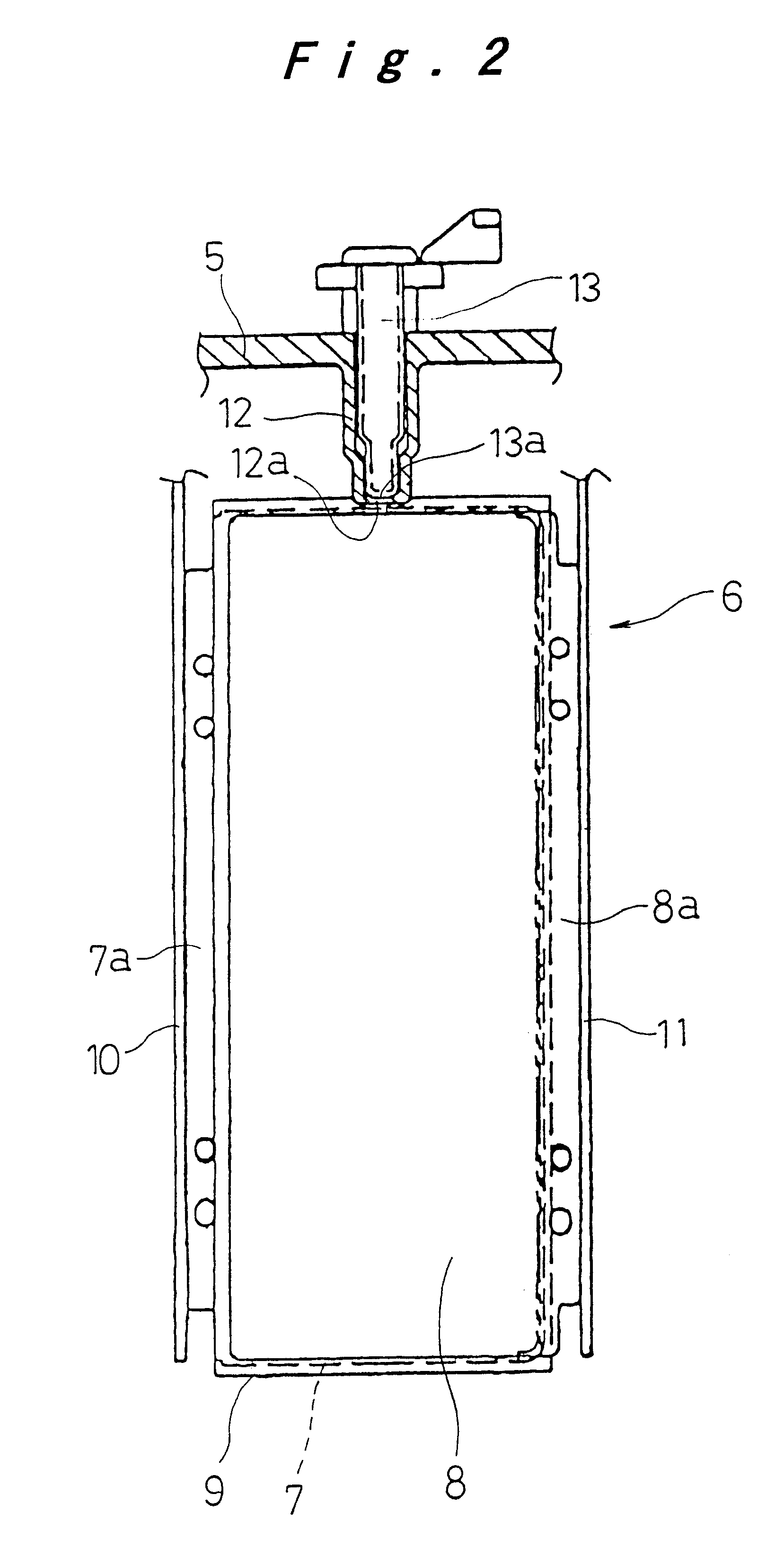
As shown in FIG. 1 and in FIG. 2, the rechargeable batteries 1 each comprise battery cases 3 made of hollow prismatic case bodies 4, of which upper open ends are closed integrally by a lid member 5. Elements for electromotive force 6 are accommodated inside each of the battery cases 3. The case bodies 4 and the lid member 5 that constitute battery cases 3 are made of a synthetic resin material, such as a PP / PPE alloy. Positive electrod...


PUM


Abstract

A temperature detection hole 12 having a bottom, which is sealed against the inside of the battery case 3 while being open to the outside, is formed in the battery case. The bottom wall 12a of the temperature detection hole is in contact with or in close proximity to the elements for electromotive force. Engaging hooks 14 are formed on lateral portions of the temperature detection hole 12 of the battery case 3, while a temperature sensor 13 is provided with elastically deformable engaging flanges 21. When the temperature sensor 13 is mounted removably in the temperature detection hole 12, the elastic restorative force of the engaging flanges 21 that are engaged in elastic deformation with the engaging hooks 14 is applied to the temperature sensor 13. The sensor end 13a of the temperature sensor 13 is thereby pressed against the bottom wall 12a of the temperature detection hole 12.

Description

1. Field of the InventionThe present invention relates to a rechargeable battery, and more particularly, to an improvement of the temperature detection portion in a sealed rechargeable battery wherein elements for electromotive force are accommodated in a sealed battery case.2. Description of Related ArtFor the temperature detection mechanism in sealed rechargeable batteries, which are used, for example, in electric vehicles, an embedded-type structure is known, wherein a temperature sensing element is integrally provided in the battery case. In order to detect the internal temperature of the battery while keeping the inside thereof airtight, a temperature detection hole having a bottom is formed in the battery case, which is sealed against the inside of the battery case and open to the outside, and a temperature sensor element is inserted into this temperature detection hole, which is then filled with a synthetic resin to integrate it into one piece with the battery case.In Japanes...

Claims


Application Information

Patent Timeline
26 Aug 2003
Publication
US6610439B1
IPC
H01M10/48; H01M2/00; H01M10/42; H01M50/569
CPC
H01M2/00; H01M10/486; Y02E60/10; H01M50/00; H01M50/569
Inventors
KIMOTO, SHINYA; WATANABE, KO