

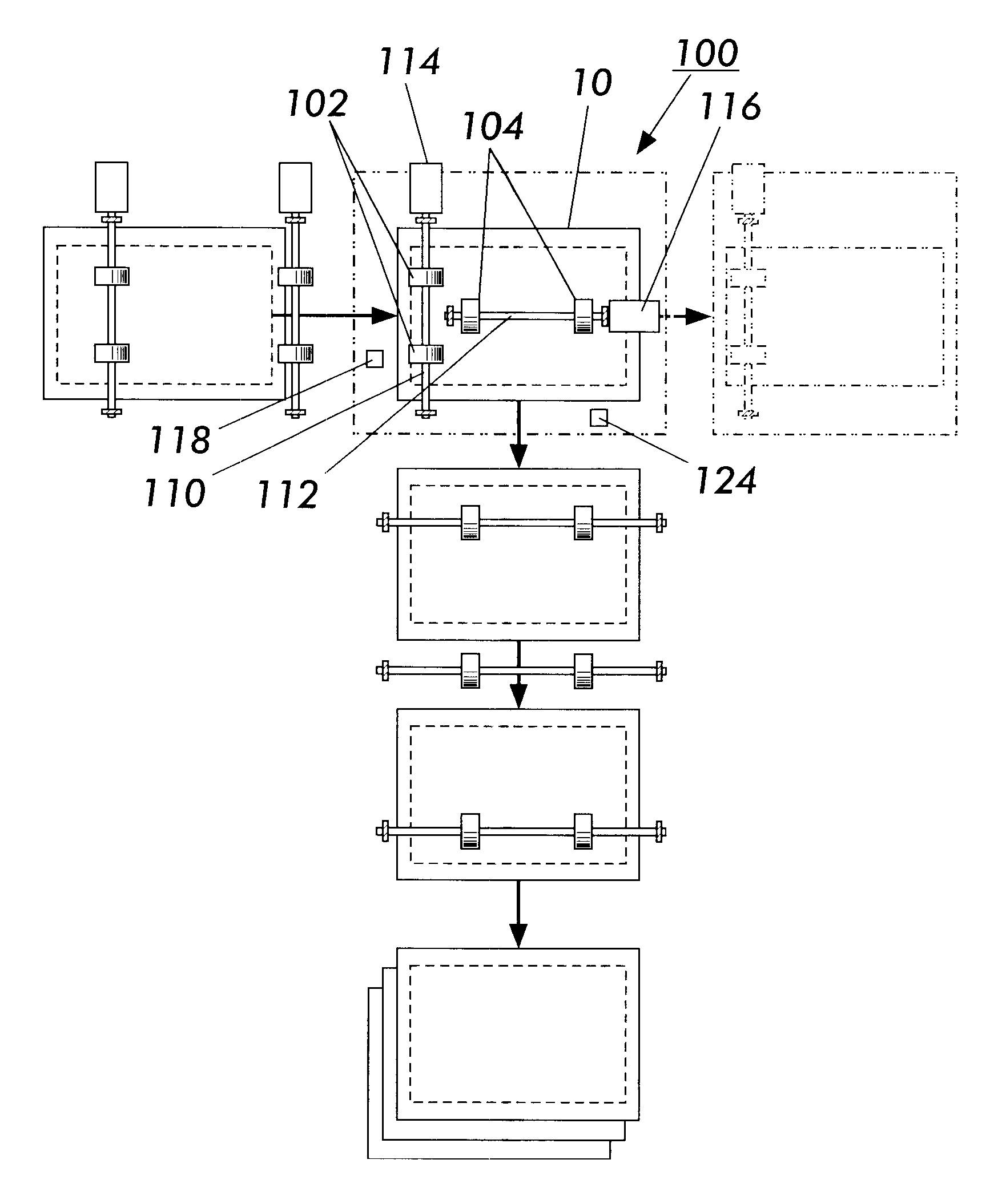
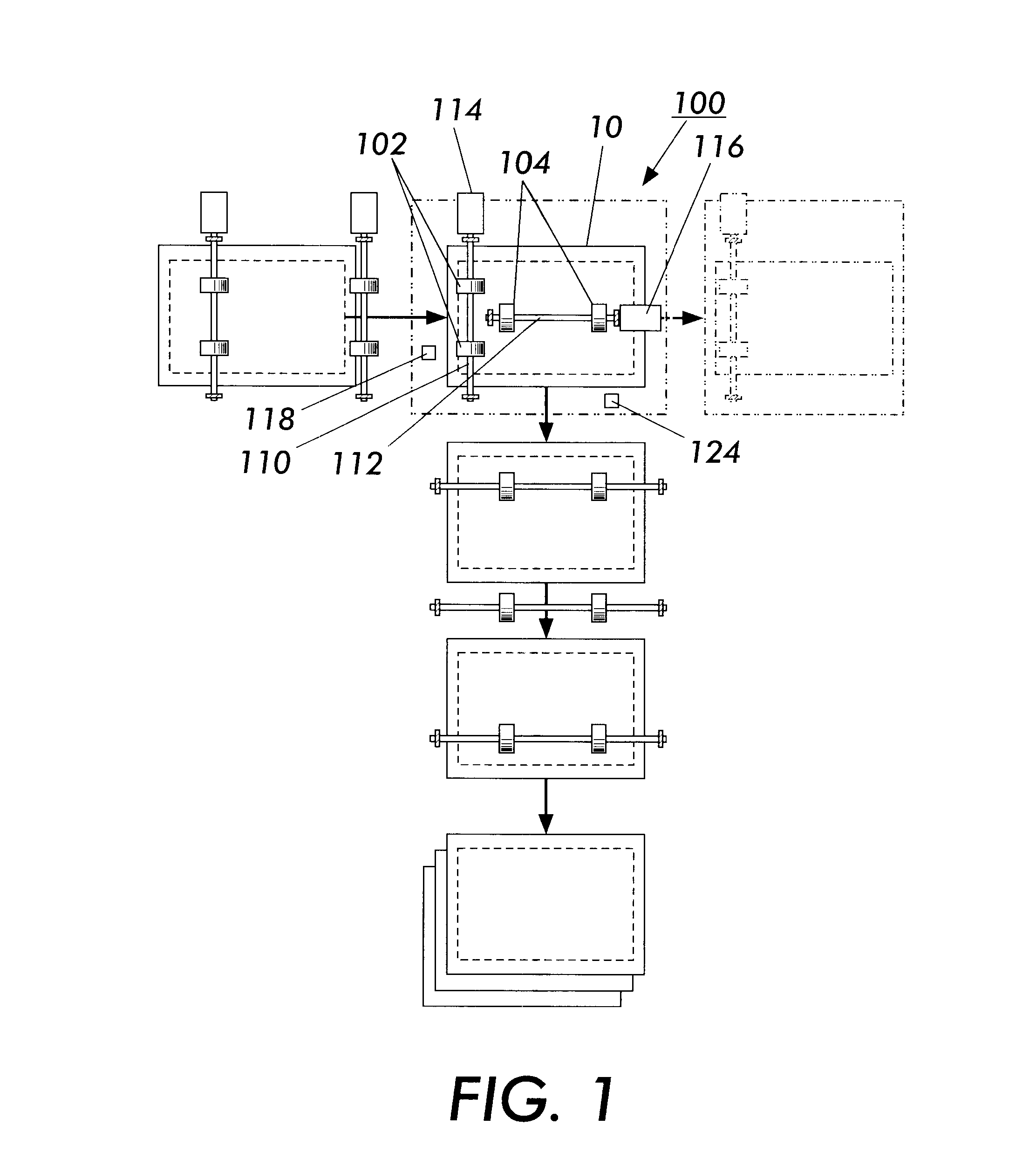
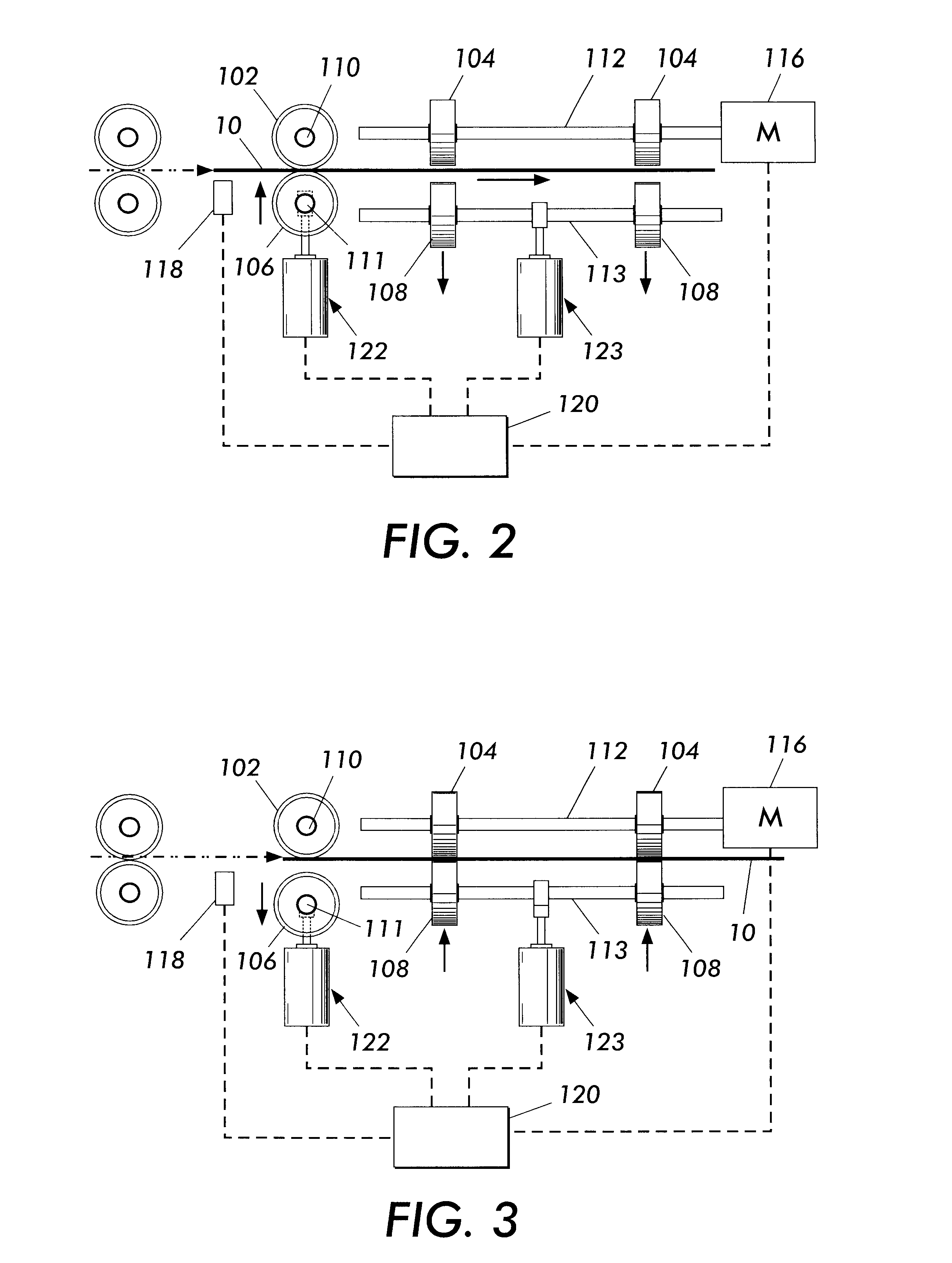
Sheet conveying device having multiple outputs
a conveying device and output technology, applied in the direction of thin material processing, article separation, article delivery, etc., can solve the problems of inability to reliably handle varying paper sizes or weights in the same job, problems such as the two-up printing of the same job, and the problem of traditional sheet sequencers and path controllers, so as to increase the output speed of the printer and increase the speed of the xerographic module
- Summary
- Abstract
- Description
- Claims
- Application Information
AI Technical Summary
Benefits of technology
Problems solved by technology
Method used
Image

Examples
Embodiment Construction
While the present invention will be described with reference to specific embodiments thereof, it will be understood that the invention is not to be limited to these embodiments. On the contrary, it is intended that the present invention cover all alternatives, modifications, and equivalents as may be included within the spirit and scope of the invention as defined by the appended claims. Other aspects and features of the present invention will become apparent as the description proceeds, wherein like reference numerals have been used throughout to designate identical elements. It is further noted that all references cited in this specification, and their references, are hereby incorporated by reference where appropriate for relevant teachings of additional or alternative details, features, and / or technical background.
In the following paragraphs, I have used the term paper generally for toner receivers. It will be apparent to those with skill in the art that other materials such as p...
PUM
| Property | Measurement | Unit |
|---|---|---|
| angle | aaaaa | aaaaa |
| speed | aaaaa | aaaaa |
| photoconductive | aaaaa | aaaaa |
Abstract
Description
Claims
Application Information