
Battery cooling structure

a cooling structure and battery technology, applied in the direction of secondary cells servicing/maintenance, deferred-action cells, electrical equipment, etc., can solve the problems of non-uniform charge condition of the cells, and large temperature difference between the cells

Inactive Publication Date: 2003-09-02
TOKYO R & D LTD
View PDF5 Cites 42 Cited by
  • Summary
  • Abstract
  • Description
  • Claims
  • Application Information

AI Technical Summary

Benefits of technology

the open air introduced from said first introduction opening in the other of said cases is discharged from said second discharge opening in one of said cases. Thereby, high space efficiency can be realized, and at the same time, capacity of the battery can be made larger.
Furthermore, by doing this, it is possible to make the temperatures of the batteries increase rapidly without generating a temperature difference between the batteries. As a result, it becomes possible to make the batteries exhibit desired performance extremely rapidly.

Problems solved by technology

However, even though heat values of the respective cells are equal to each other, a large temperature difference between the cells sometimes occurs.
As a result, a considerable temperature difference occurs between both cells.
And, this temperature difference makes charge condition of the cells non-uniform.
In other words, the temperature difference between the cells causes performance reduction of the battery.
Accordingly, a cooling ratio by means of the open air never becomes uniform, and the above-described tasks, namely, the task that the performance of the battery is reduced due to the temperature difference between the cells cannot be substantially solved.
As known well, the batteries cannot exhibit their desired performance if their temperatures are too low.

Method used


Image

  • Battery cooling structure
  • Battery cooling structure
  • Battery cooling structure

Examples


first embodiment

Below, the present invention will be explained using FIG. 1 to FIG. 9.

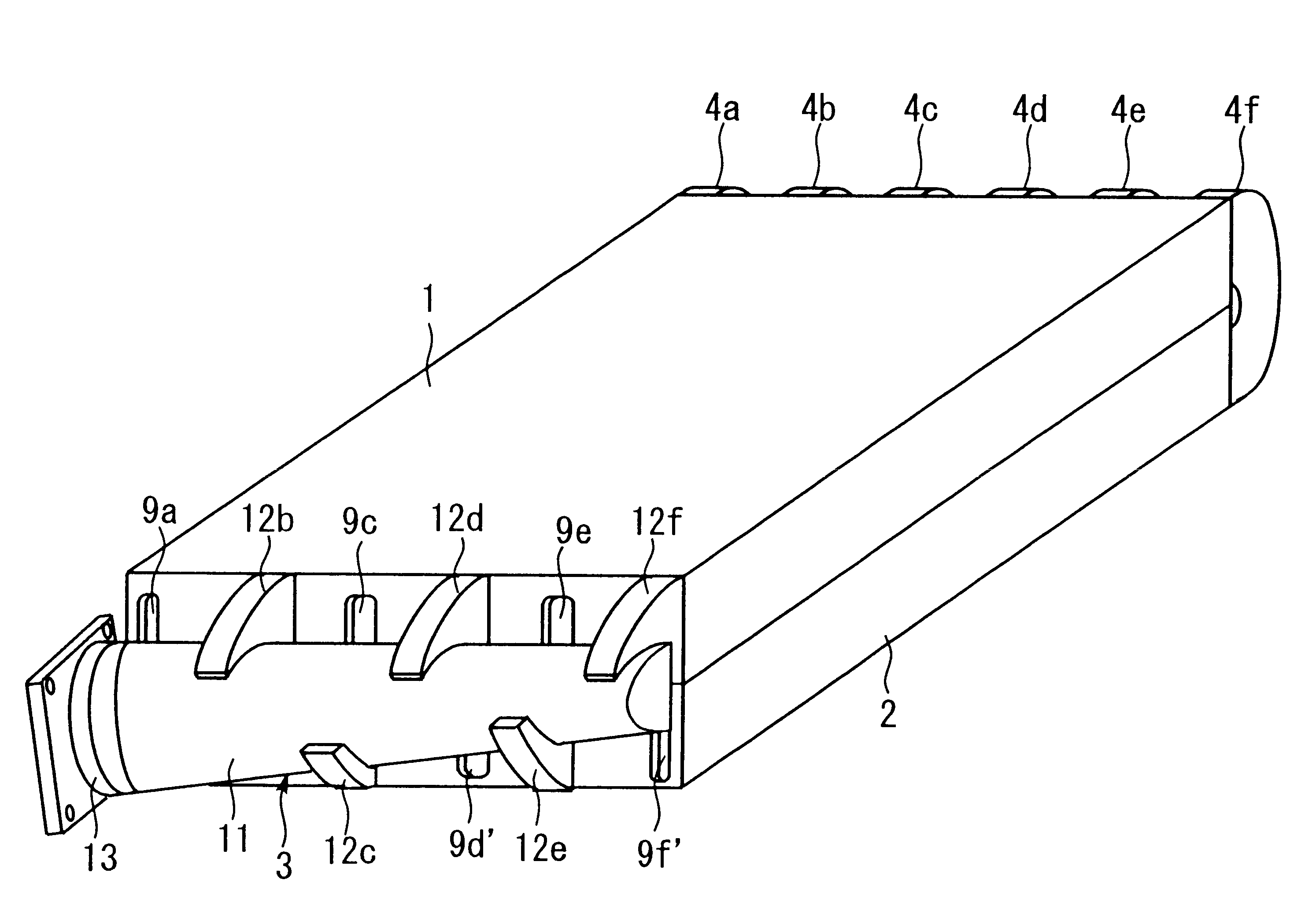
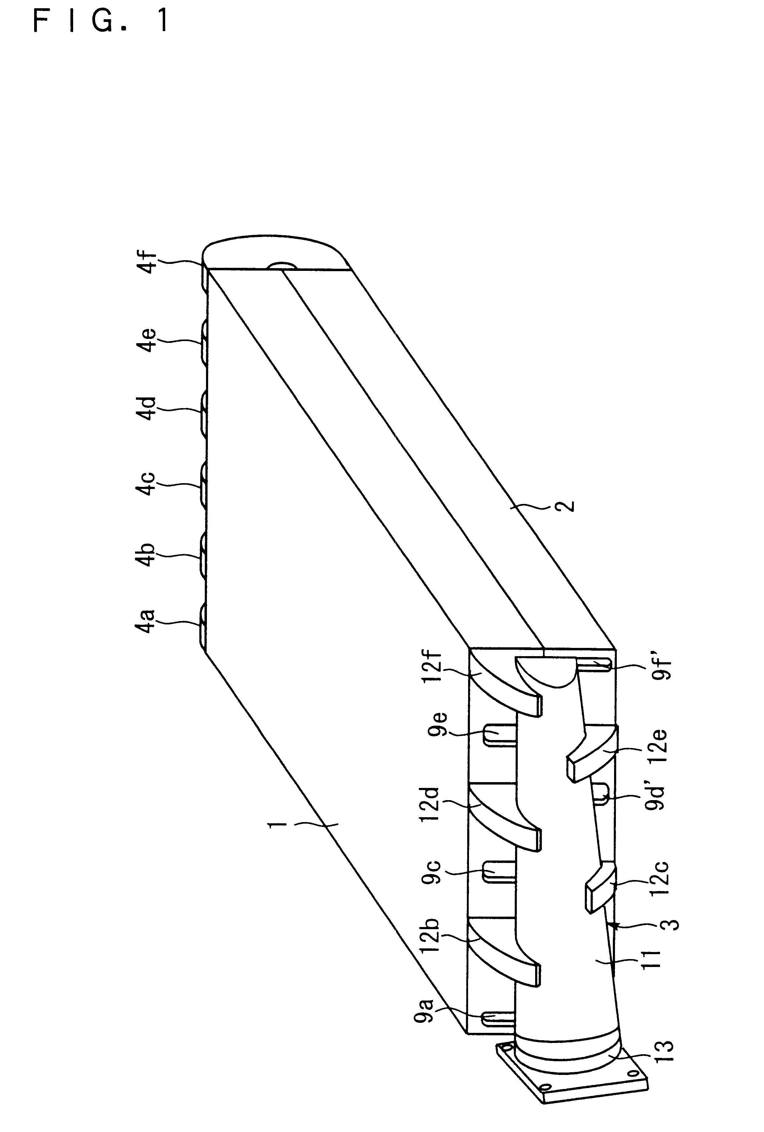
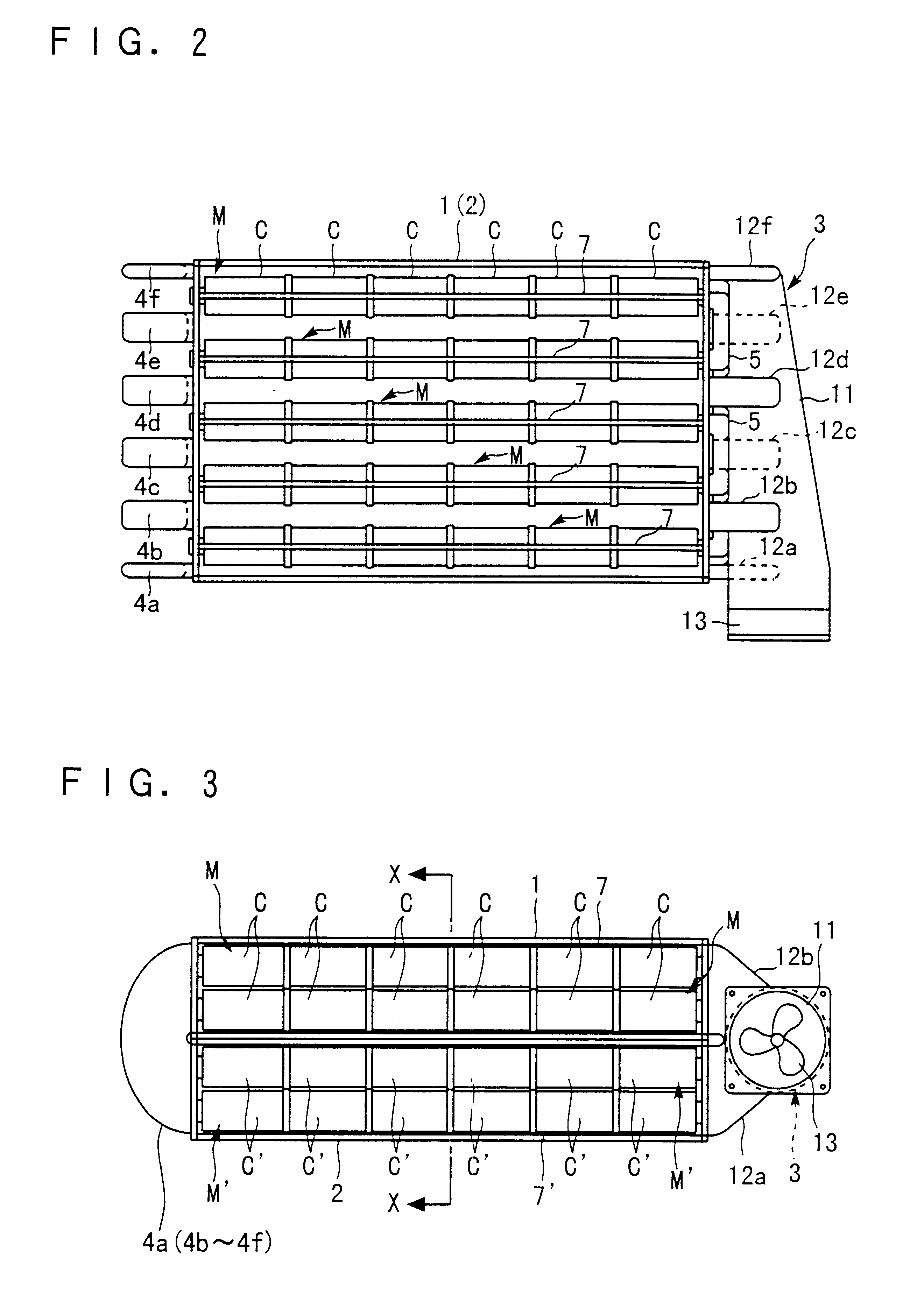
In addition, FIG. 1 is an appearance view of a battery unit in which a cooling structure related to this embodiment of the present invention is adopted, FIG. 2 is a plane view of the same battery unit with a roof plate omitted, FIG. 3 is a front view of the same battery unit with a front plate omitted, FIG. 4 and FIG. 5 are a right-hand side view and a left-hand side view of the same battery unit, respectively, FIG. 6 is a transverse cross sectional view of the same battery unit, which is taken along an X--X line in FIG. 3, FIG. 7 is a plane view of the same battery unit with a roof plate omitted, which shows a flow situation of introduced open air, FIG. 8 is a plane view of the same battery unit with a bottom plate omitted, which shows a flow situation of introduced open air, and FIG. 9 is a front view of the same battery unit with a front plate omitted, which shows a flow situation of introduced open air.

The app...

second embodiment

Next, the present invention will be explained by using FIG. 10 and FIG. 11.

In addition, FIG. 10 is an essential plane view of a battery unit in which a cooling structure related to this embodiment is adopted, and FIG. 11 is an essential front view of the battery unit in which a cooling structure related to this embodiment is adopted.

However, in FIG. 10 and FIG. 11, similar to the previous first embodiment, a roof plate and a front plate of the case are omitted. Also, in this embodiment, its basic technical idea is the same as that of the above-described first embodiment. Accordingly, explanation below will be focused on points different from this first embodiment. In addition, with regard to members having a shape and a function same as those explained in connection with the first embodiment, codes same as those being already used are attached thereto, and the explanation thereof will be omitted.

The battery cooling structure (referred to as this cooling structure again, hereinafter)...


PUM


Abstract

A battery cooling structure for cooling modules (battery elements) M by means of open air, which are accommodated within a case 1, has the following arrangement: First, a space within the case 1 is partitioned, and a first space 8b and a second space 8a adjacent to each other and interposing the modules M therebetween are formed. And, on a surface of the case 1, which corresponds to one end side of the modules M, a first introduction opening 9b is formed, and on a surface of the case 1, which corresponds to the other end side of the modules M, a first discharge opening 10b is formed for discharging open air introduced into the first space 8b from this first introduction opening 9b after this open air has passed the inside of the first space 8b. On the other hand, on the surface of the case 1, which corresponds to the other end side of the modules M, a second introduction opening 9a is formed. Further, on the surface of the case 1, which corresponds to one end side of the modules M, a second discharge opening 10a is formed for discharging open air introduced into the second space 8a from this second introduction opening 9a after this open air has passed the inside of the second space 8a.

Description

The present invention relates to a cooling structure for battery that is loaded in motor type vehicles such as a motor two-wheel vehicle.BACKGROUND TECHNOLOGYIn recent years, research and development of motor type vehicles irrespective of a two-wheel vehicle or a four-wheel vehicle are actively conducted for coping with an environment issue. Especially as for the four-wheel vehicle advantageous from a space aspect, there is an example that is already being put to practical use.By the way, in such motor type vehicles, especially a motor two-wheel vehicle out of them, in which it is severely required to make a power supply thereof compact, is loaded with a high-performance battery such as a nickel-hydrogen battery, a nickel-cadmium battery and lithium ion battery. More particularly, first a module is obtained by connecting several cells to each other in series. Next, a predetermined number of these modules are closely accommodated within a hard case. And, finally, these modules are co...

Claims


Application Information

Patent Timeline
IPC IPC(8): H01M10/50H01M10/42
CPCH01M10/5004H01M10/5016H01M10/503H01M10/5071H01M10/5073H01M10/613H01M10/625H01M10/643H01M10/6565H01M10/6566Y02E60/10H01M10/6556
Inventor WATANABE, OSAMU
Owner TOKYO R & D LTD
Learn More