
Electron gun arrangements having closely spaced cathode and electrode and a vacuum seal

a vacuum seal and cathode technology, applied in the direction of cathode ray tubes/electron beam tubes, tubes with multiple resonators, electric discharge tubes, etc., can solve the problems of vacuum destruction, cracks at joints between,

Inactive Publication Date: 2003-09-02
E2V TECH (UK) LTD
View PDF14 Cites 1 Cited by
  • Summary
  • Abstract
  • Description
  • Claims
  • Application Information

AI Technical Summary

Benefits of technology

As the electrode support is mounted on a mount of low thermal expansivity it ensures that very little movement occurs at the support during thermal cycling. In a preferred embodiment, the mount is of Kovar. Kovar is a U.S. registered trademark No. 337,962 identifying the source of an alloyed metal. The registration is currently owned by CRS Holdings, Inc. of Wilmington, Del. It is thus possible to maintain accurately the predetermined required distance between the electrode and the cathode. The electrode may be a control grid located closely adjacent the front surface of the cathode or could, for example, be a focus electrode. The mount is included as part of the vacuum envelope, making a vacuum seal with the flexible member but is not required to take up any movement due to thermal expansion. Thus there is effectively a decoupling between the electrical and the mechanical considerations of the arrangement. The accuracy requirements for the electrical components can be separated from maintenance of the vacuum envelope. The invention achieves this and yet provides a relatively simple arrangement in which it is not necessary to provide a completely separate structure for mounting the electrodes of the electron bun from the vacuum envelope. Thus the construction is also relatively compact.
Use of the invention provides a compact arrangement with a relatively small number of components which nevertheless permits optimization of both electrical / microwave properties of the device and the mechanical aspects.

Problems solved by technology

If all the components making up the vacuum envelope were rigid it is likely that cracks would occur at joints between them and the vacuum is destroyed.

Method used


Image

  • Electron gun arrangements having closely spaced cathode and electrode and a vacuum seal
  • Electron gun arrangements having closely spaced cathode and electrode and a vacuum seal

Examples


Embodiment Construction

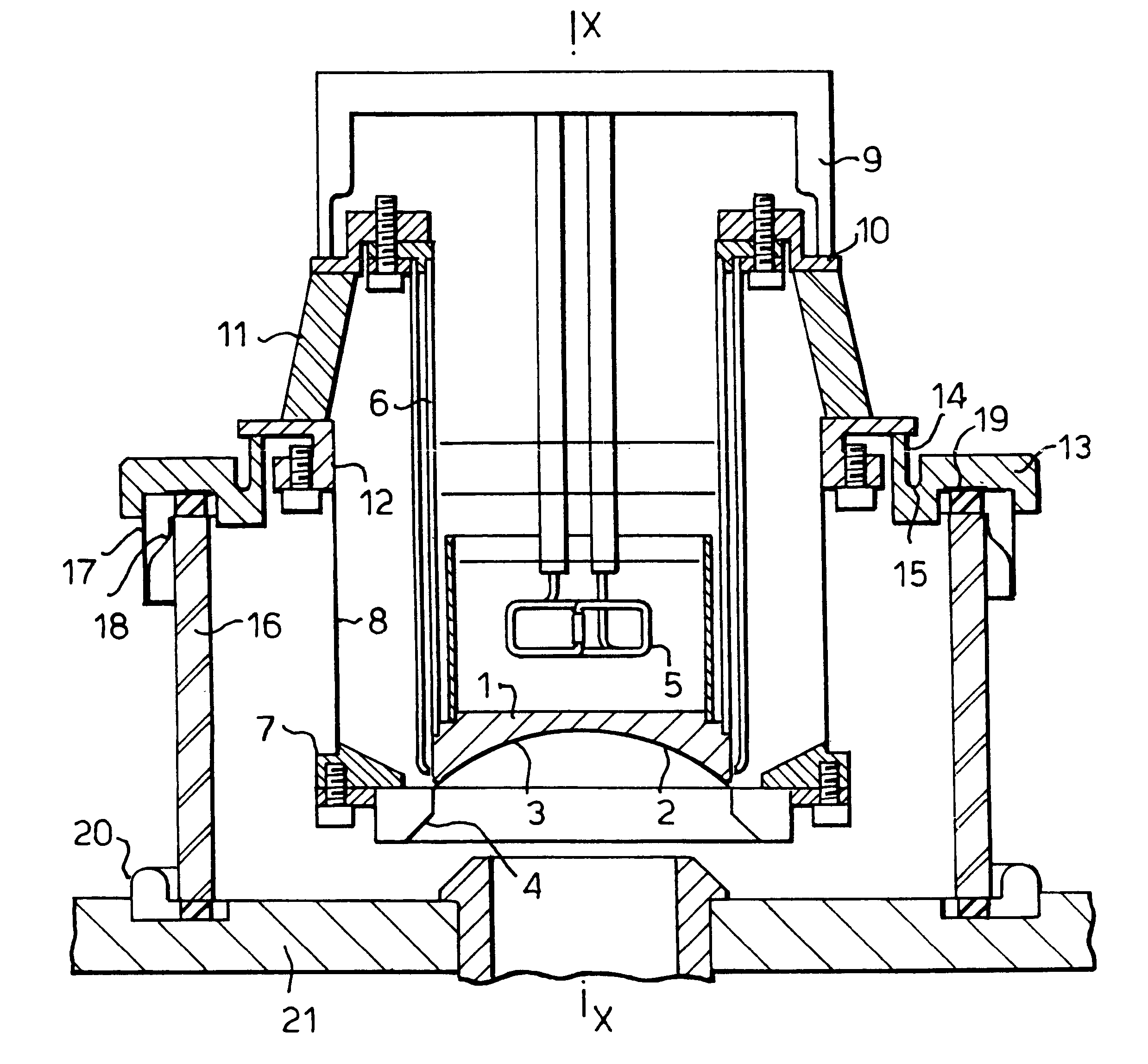
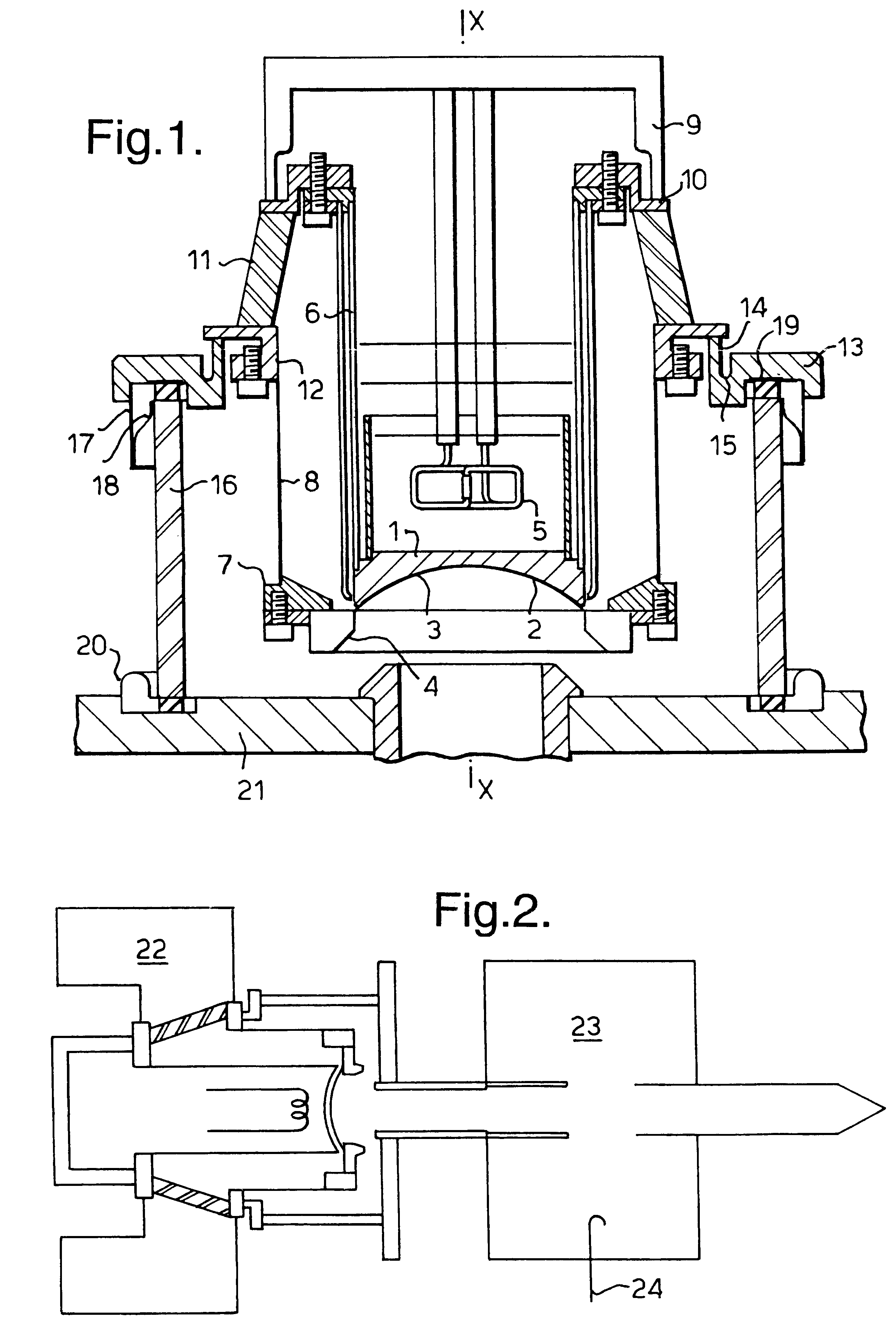
With reference to FIG. 1, an electron gun arrangement comprises a cathode 1 having a curved front surface 2 in front of which is located a curved control grid 3 closely spaced therefrom and conforming to the profile of the cathode front surface 2. An annular focus electrode 4 is located in front of the cathode 2. A heater 5 is located behind the cathode 1 and during use causes the temperature of the cathode 1 to be raised to a temperature sufficiently high for electrons to be emitted from the front surface 2. The cathode 1 is supported by a cylindrical cathode support 6. The control grid 3 and focus electrode 4 are mounted on a common grid mount 7 which is annular and arranged about the cathode 1. The grid mount 7 is supported by a grid mount support 8 which is also cylindrical and coaxially surrounds the cathode support 6.

The electron gun assembly is contained within a vacuum envelope which is partially defined by an end portion 9 which is mounted on a Kovar support 10 to give a va...


PUM


Abstract

An electron gun arrangement includes a cathode having a front surface and control grid located in front of it. The control grid is mounted via a cylindrical support on a Kovar mount. The cathode is supported by a cylindrical support mounted on a Kovar support. Ceramic material being located between the two supports. The vacuum envelope within which the electron gun is contained includes the Kovar support and a flexible member with which it makes a vacuum seal, this member being of copper. The copper member is sealed to a ceramic cylinder via metal flanges. The assembly permits the spacing between the cathode and grid to be maintained while the copper member permits thermal expansion to occur to maintain vacuum integrity.

Description

This invention relates to electron gun arrangements and more particularly, but not exclusively, to arrangements suitable for use in inductive output tubes (IOTs).In electron gun assemblies used in IOTs and other types of gridded electron beam tubes, it is necessary to be able to accurately space apart the cathode at which the electron beam is generated and the electrode or electrodes located in front of the cathode to control the profile and / or density of the electron beam. The present invention seeks to provides an electron gun arrangement which permits close spacing to be maintained with accuracy between the cathode and adjacent electrode or electrodes and also provides a good mechanical construction.SUMMARY TO THE INVENTIONAccording to the invention, there is provided an electron gun arrangement comprising: a vacuum envelope containing a cathode and an electrode located in front of the cathode; an electrode support mounted on a mount of low thermal expansivity; and a flexible mem...

Claims


Application Information

Patent Timeline
Patent Type & Authority Patents(United States)
IPC IPC(8): H01J23/02H01J23/065
CPCH01J23/065H01J2225/04
Inventor THWAITES, ALFRED CHRISTOPHERCARR, DAVID WARDBARDELL, STEVENCOX, PETER ROBERT JOHN
Owner E2V TECH (UK) LTD
Learn More