Transmission line, integrated circuit, and transmitter receiver

a technology of integrated circuits and transmitters, applied in the direction of coupling devices, electrical devices, waveguides, etc., can solve the problems of inability to obtain suitable transmission characteristics, inability to receive the necessary signal on the surface of the electrode circuit, and disadvantageous increase of the conductor

Inactive Publication Date: 2003-09-02
MURATA MFG CO LTD
View PDF8 Cites 14 Cited by
  • Summary
  • Abstract
  • Description
  • Claims
  • Application Information

AI Technical Summary

Benefits of technology

In order to achieve the above-described object, a dielectric-waveguide-type transmission line according to the present invention comprises: a dielectric substrate; protrusions provided in line, one after another, on at least one main surface of the dielectric substrate; electrodes formed on both main surfaces of the dielectric substrate and on the outer surfaces of the protrusions; a plurality of through-holes for connecting the electrodes, the plurality of through holes being aligned along both sides of the protrusions; an interrupting unit for dividing the transmission line into transmission line segments to interrupt a transmission signal; and a circuit for coupling the transmission line segments separated by the interrupting unit, the circuit being provided on the other main surface of the dielectric substrate. With this arrangement, a signal carried by the transmission line is also directed through the circuit provided on the main surface of the dielectric substrate, and the signal can be prevented from leaking between the protrusions.
The transmission line may further comprise other through-holes for connecting the electrodes, the other through-holes being provided in an area for interrupting the transmission signal. With this arrangement, the transmission of the signal between the transmission line segments can be effectively suppressed.
Also, one of the protrusions at one transmission line segment may have a different height from the other protrusion at the other transmission line segment. Accordingly, leakage of the signal transmitted from the input-side of the transmission path to the output-side of the transmission path can be suppressed even when the frequency of the signal input to the electrode circuit formed on the main surface of the dielectric substrate is different from the frequency of the signal output from the electrode circuit.
Further, an integrated circuit according to the present invention comprises the above-described transmission line, electronic components mounted on the other main surface of the dielectric substrate, and a circuit for connecting the electronic components. With this arrangement, an integrated circuit having excellent input / output characteristics and transmission characteristics can be obtained.
Further, a transmitter-receiver according to the present invention comprises one of the above-described transmission line and the integrated circuit. Accordingly, a transmitter-receiver having excellent transmission characteristics can be provided.

Problems solved by technology

Accordingly, current concentrates at the through-holes or the via-holes and thus conductor loss disadvantageously increases.
In this case, suitable transmission characteristics cannot be obtained, as compared to a common waveguide or dielectric-filled waveguide.
Also, since a signal is directly transmitted from a portion of the dielectric waveguide functioning as an input unit to a portion of the dielectric waveguide functioning as an output unit, the surface-electrode circuit cannot receive the necessary signal.
Accordingly, circuit elements mounted on the surface-electrode circuit cannot obtain the required output characteristics.
Further, the signal which is directly transmitted from the input unit to the output unit interferes with an output signal from the surface-electrode circuit, and thus transmission characteristics suitable for an integrated circuit cannot be obtained.

Method used


Image

  • Transmission line, integrated circuit, and transmitter receiver
  • Transmission line, integrated circuit, and transmitter receiver
  • Transmission line, integrated circuit, and transmitter receiver

Examples


first embodiment

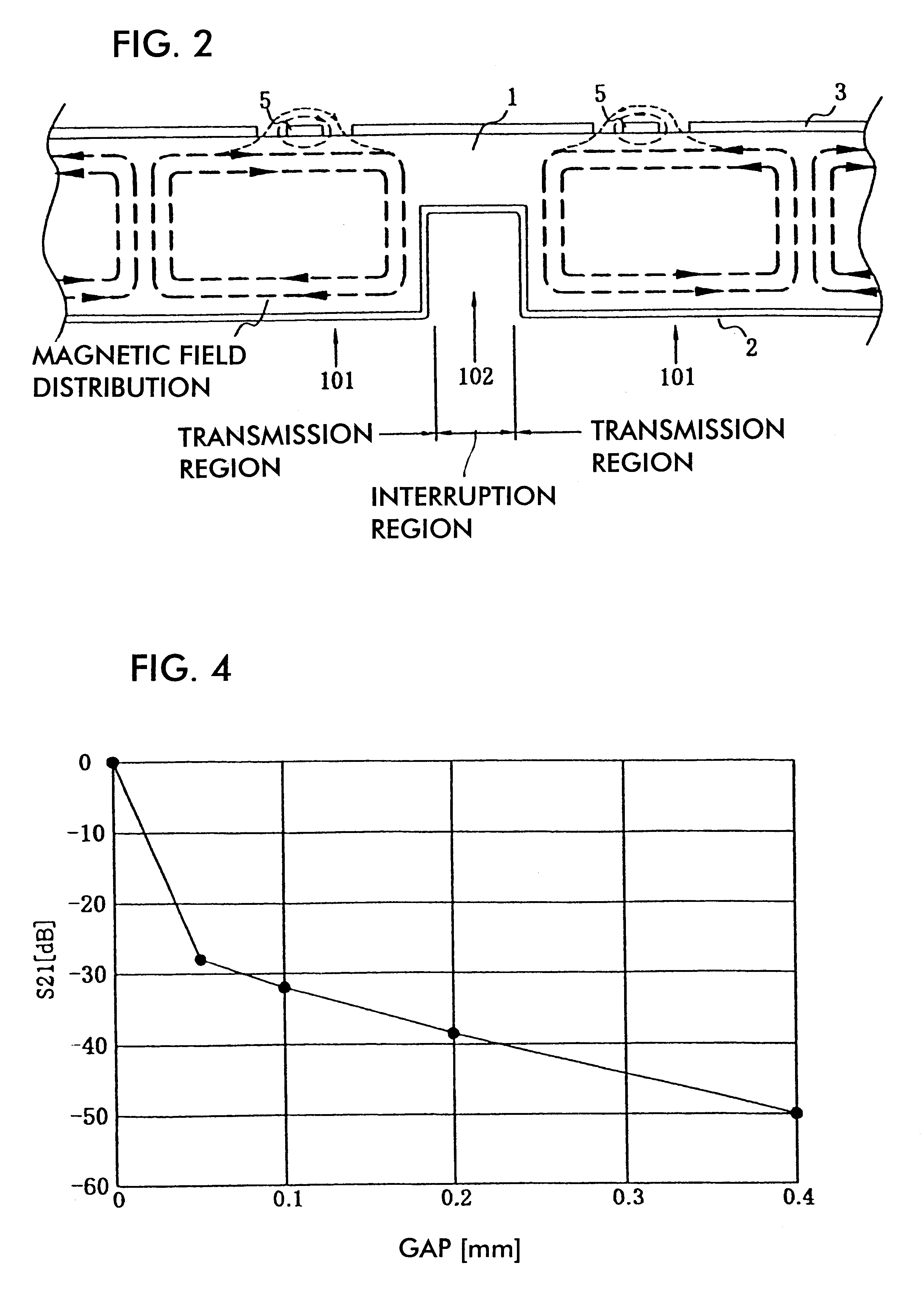
Hereinafter, the configuration of a transmission line will be described with reference to FIGS. 1A to 4.

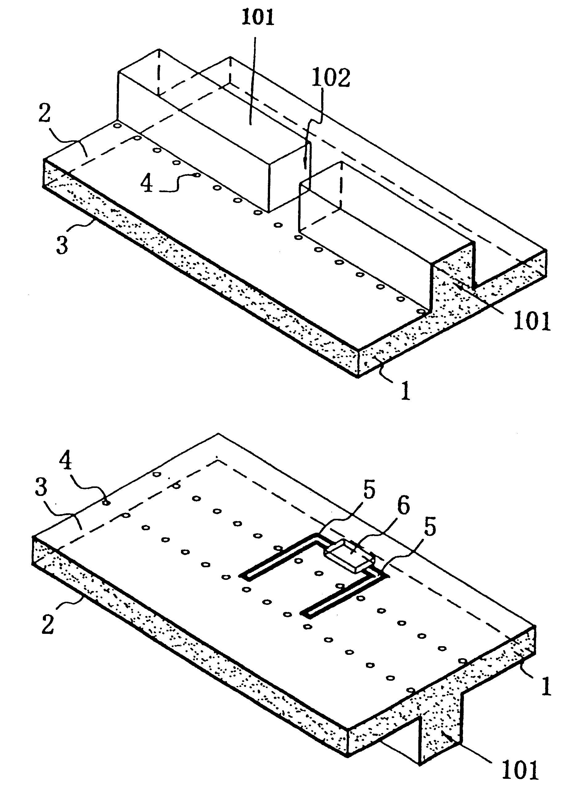
FIGS. 1A and 1B are perspective views of the transmission line wherein FIG. 1A shows a lower side and FIG. 1B shows an upper side.

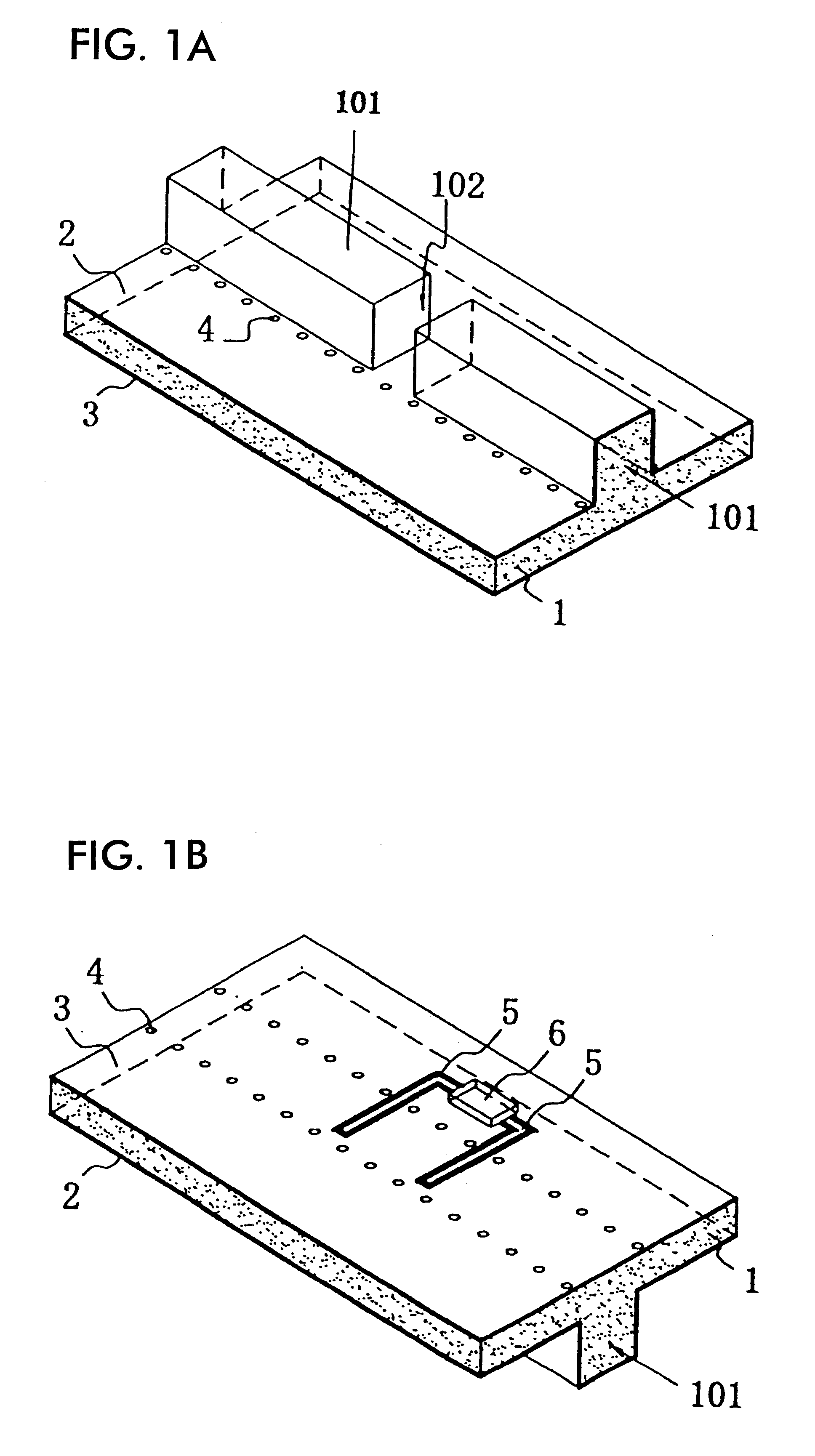
In FIGS. 1A and 1B, a dielectric substrate 1, a lower-surface electrode 2, an upper-surface electrode 3, through-holes 4, coplanar lines 5, a circuit element 6, protrusions 101, and a discontinuous portion 102 are shown.

The protrusions 101 extend in line one after another in a direction perpendicular to the cross section in a part of the dielectric substrate 1, with the discontinuous portion 102 therebetween. The lower-surface electrode 2 is formed on a main surface of the dielectric substrate 1 provided with the protrusions 101 and on the outer surfaces (side surfaces and upper surface) of the protrusions 101. The upper-surface electrode 3 is formed on substantially the whole area of the surface that is opposite to the lower-surface electrode 2. Furth...

second embodiment

Subsequently, the configuration of a transmission line will be described with reference to FIG. 5.

FIG. 5 is a perspective view of the transmission line.

In FIG. 5, the dielectric substrate 1, the lower-surface electrode 2, the upper-surface electrode 3, the through-holes 4, the protrusions 101, and a protrusion 103 are shown.

In the transmission line shown in FIG. 5, the protrusion 103, whose height is lower than that of the protrusions 101, is provided between the protrusions 101. The configuration of the transmission line is otherwise the same as the one shown in FIGS. 1A and 1B. The protrusion 103 is formed such that the distance from the upper-surface electrode 3 of the dielectric substrate 1 to the lower surface of the protrusion 103 is shorter than 1 / 2 of the wavelength of a transmission signal. Accordingly, the height of the H surface decreases, the cut-off frequency of the transmission path increases, the TE.sub.10 mode is interrupted at the protrusion 103, and thus electroma...

third embodiment

Next, the configuration of a transmission line will be described with reference to FIG. 6.

FIG. 6 is a perspective view of the transmission line.

In FIG. 6, the dielectric substrate 1, the lower-surface electrode 2, the upper-surface electrode 3, the through-holes 4, the protrusions 101, and indented portions 104 are shown.

In the transmission line shown in FIG. 6, the indented portions 104 are provided between the protrusions 101 which extend one after another, such that the indented portions 104 are recessed at the two sides in the width direction of the protrusions 101. The configuration of the transmission line is otherwise the same as the one shown in FIGS. 1A and 1B.

In this configuration, the operation is the same as that of the transmission line shown in FIG. 5, utilizing the TE.sub.10 mode in which the electromagnetic fields are turned by 90 degrees. The indented portions 104 contribute to suppress leakage between the protrusions 101, and thus the transmission characteristic o...


PUM


Abstract

In a transmission line, protrusions extend in line one after another in a direction perpendicular to the cross section in a part of a dielectric substrate, with a discontinuous portion therebetween. A lower-surface electrode is formed on a main surface of the dielectric substrate provided with the protrusions and on the outer surfaces of the protrusions. An upper-surface electrode is formed on substantially the whole area of the surface opposite to the lower-surface electrode. Further, a plurality of through-holes for connecting the lower-surface electrode and the upper-surface electrode, which are formed on both surfaces of the dielectric substrate, are aligned on both sides of the protrusions along the direction in which the protrusions extend. Also, coplanar lines and a circuit element are mounted on the upper-surface electrode. The coplanar lines are coupled at a predetermined position to a transmission path formed by the protrusions.

Description

1. Field of the InventionThe present invention relates to a transmission line formed in a dielectric substrate, an integrated circuit having the dielectric substrate, and a transceiver such as a radar device or a communication device including the integrated circuit.2. Description of the Related ArtExamples of waveguide-type transmission lines which are integrated with dielectric substrates are disclosed in (1) Japanese Unexamined Patent Application Publication No. 6-53711 and (2) Japanese Unexamined Patent Application Publication No. 10-75108.According to (1), a dielectric substrate has two or more conductor layers and a plurality of conductive through-holes which are aligned in two lines and which connect the conductor layers. The portion between the two conductor layers and between the two lines of through-holes functions as a waveguide (dielectric-filled waveguide). In a dielectric waveguide line and a wiring substrate according to (2), in addition to the construction of (1), su...

Claims


Application Information

Patent Timeline
Patent Type & Authority Patents(United States)
IPC IPC(8): H01P3/12H01P5/107H01P5/10H01P3/00H01P3/16H01P3/123H01P5/02H01P5/08
CPCH01P3/12H01P3/165H01P5/107
Inventor YAMASHITA, SADAOHIRATSUKA, TOSHIROSAITOH, ATSUSHIOKANO, TAKESHI
Owner MURATA MFG CO LTD
Why Eureka
Try Eureka