

Air inlet for ATV
a technology for air inlets and atvs, which is applied in the direction of combustion-air/fuel-air treatment, machines/engines, cycle equipment, etc., can solve the problems of large friction heat generated by the transmission, disadvantageously defining a volume of stagnant air, and increasing temperatures around the transmission
- Summary
- Abstract
- Description
- Claims
- Application Information
AI Technical Summary
Benefits of technology
Problems solved by technology
Method used
Image

Examples
Embodiment Construction
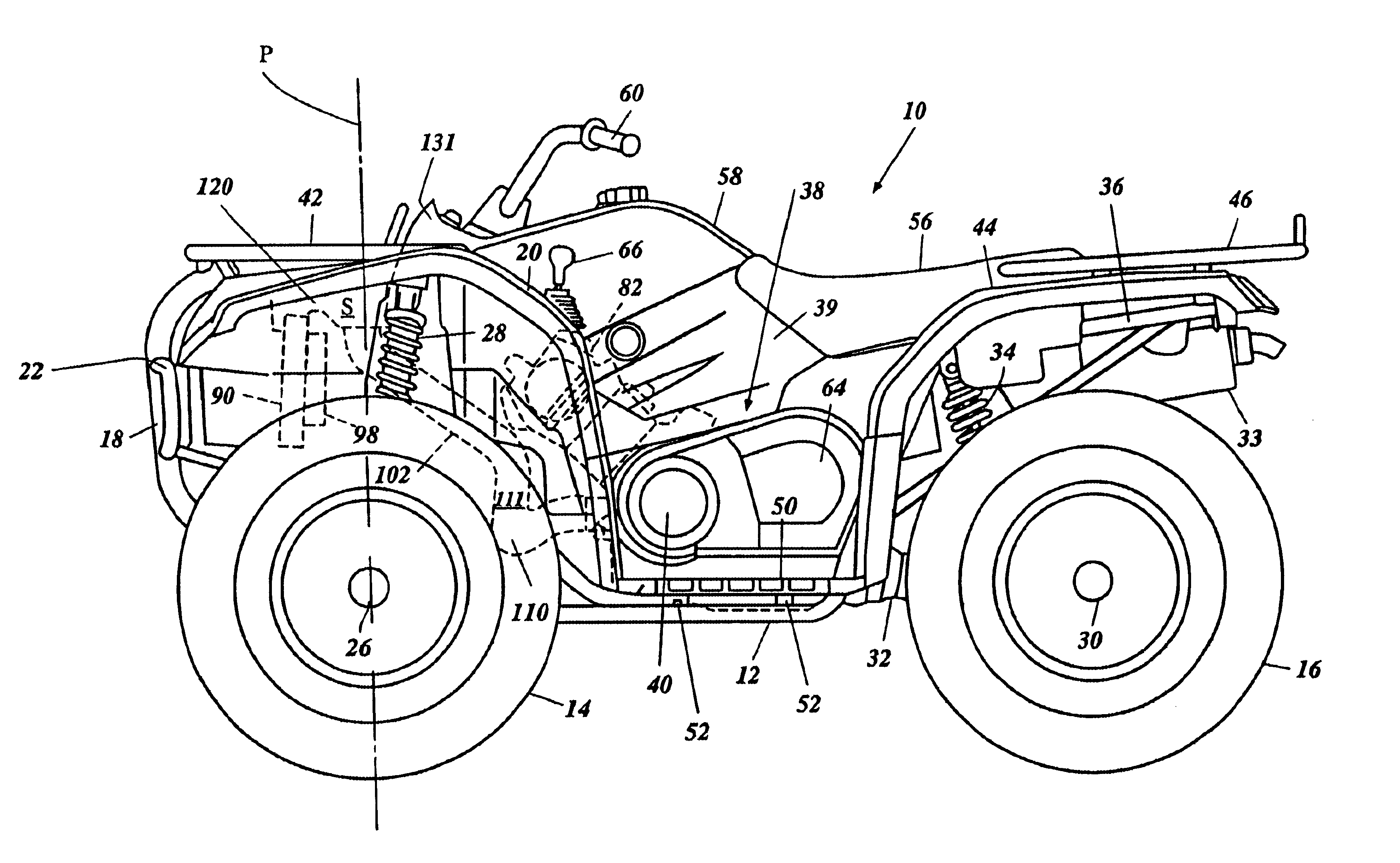
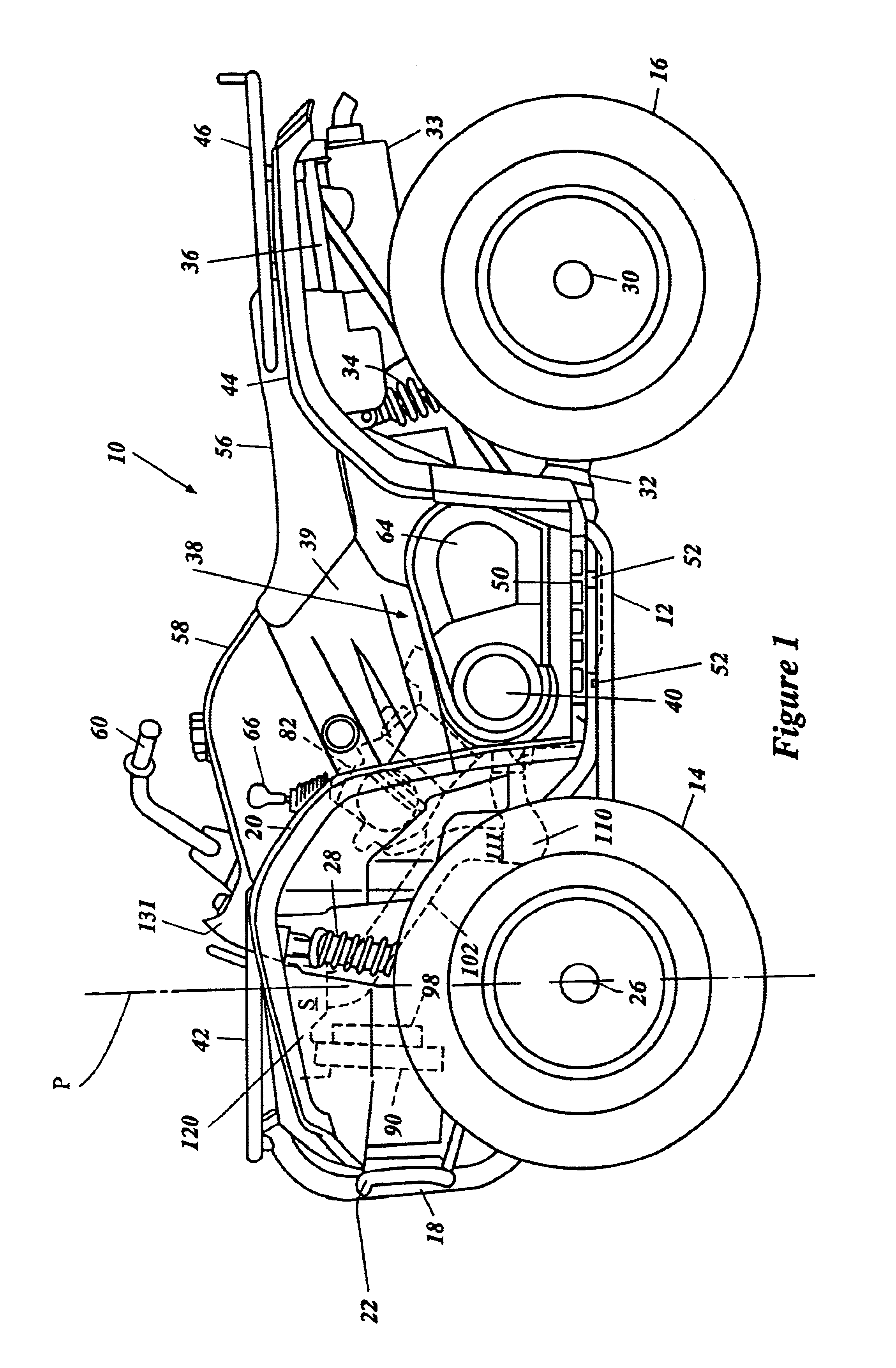
With reference now to FIG. 1, an offroad or all terrain vehicle, which is generally indicated by the reference numeral 10, is illustrated therein. The vehicle 10 preferably is arranged and configured in accordance with certain features, aspects and advantages of the present invention. More particularly, the vehicle 10 preferably comprises a transmission cooling air intake system, which will be described below, that is arranged and configured in accordance with certain features, aspects and advantages of the present invention. While the present invention will be described in the context of the illustrated vehicle 10, it should be understood that the present invention may also find utility in a number of other applications. For instance, although the illustrated vehicle 10 comprises four wheels, the present invention could be used on motor vehicles having two wheels, three wheels or more than four wheels. In addition, the present invention can also be used on vehicles having runners a...
PUM
 Abstract
Description
Claims
Application Information