
Ink jet printhead having thermal bend actuator heating element electrically isolated from nozzle chamber ink

a technology of thermal bend actuator and thermal insulation element, which is applied in printing and other directions, can solve the problems of power consumption, limited nozzle packing density, and insufficient power consumption to meet the requirements of application

Inactive Publication Date: 2003-09-23
MEMJET TECH LTD +1
View PDF11 Cites 48 Cited by
  • Summary
  • Abstract
  • Description
  • Claims
  • Application Information

AI Technical Summary

Problems solved by technology

This is because the two main contenders--thermal ink jet and piezoelectric ink jet--each have severe fundamental problems meeting the requirements of the application.
The most significant problem with thermal ink jet is power consumption.
This is approximately 100 times that required for these applications, and stems from the energy-inefficient means of drop ejection.
The high power consumption limits the nozzle packing density as
The most significant problem with piezoelectric ink jet is size and cost.
This is not a significant problem at the current limit of around 300 nozzles per print head, but is a major impediment to the fabrication of page width print heads with 19,200 nozzles.
A problem with this arrangement is that it is required that parts of the device be hydrophobically treated to inhibit the ingress of ink into the region of the actuator.
A danger exists that these foreign particles, such as dust particles, could fall onto the nozzle assemblies 510 adversely affecting their operation.

Method used


Image

  • Ink jet printhead having thermal bend actuator heating element electrically isolated from nozzle chamber ink
  • Ink jet printhead having thermal bend actuator heating element electrically isolated from nozzle chamber ink
  • Ink jet printhead having thermal bend actuator heating element electrically isolated from nozzle chamber ink

Examples


Embodiment Construction

The preferred embodiment is a 1600 dpi modular monolithic print head suitable for incorporation into a wide variety of page width printers and in print-on-demand camera systems. The print head is fabricated by means of Micro-Electro-Mechanical-Systems (MEMS) technology, which refers to mechanical systems built on the micron scale, usually using technologies developed for integrated circuit fabrication.

As more than 50,000 nozzles are required for a 1600 dpi A4 photographic quality page width printer, integration of the drive electronics on the same chip as the print head is essential to achieve low cost. Integration allows the number of external connections to the print head to be reduced from around 50,000 to around 100. To provide the drive electronics, the preferred embodiment integrates CMOS logic and drive transistors on the same wafer as the MEMS nozzles. MEMS has several major advantages over other manufacturing techniques:

mechanical devices can be built with dimensions and ac...


PUM


Abstract

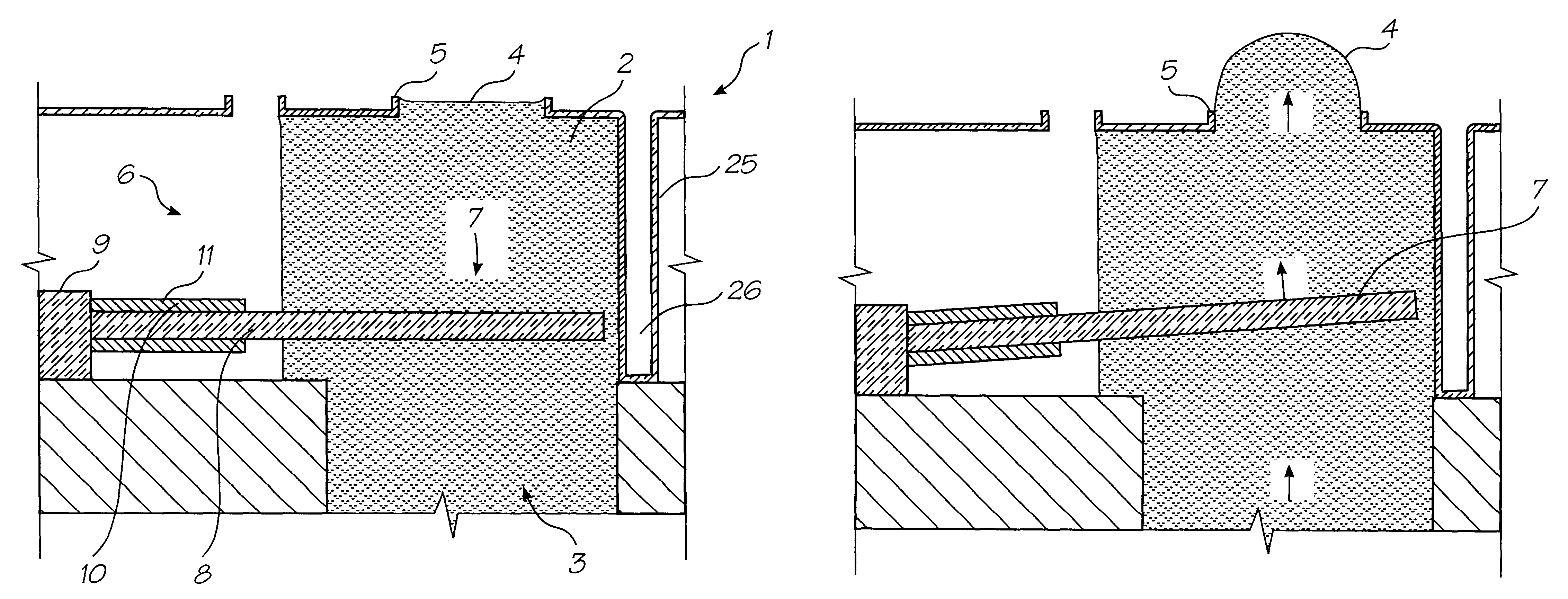
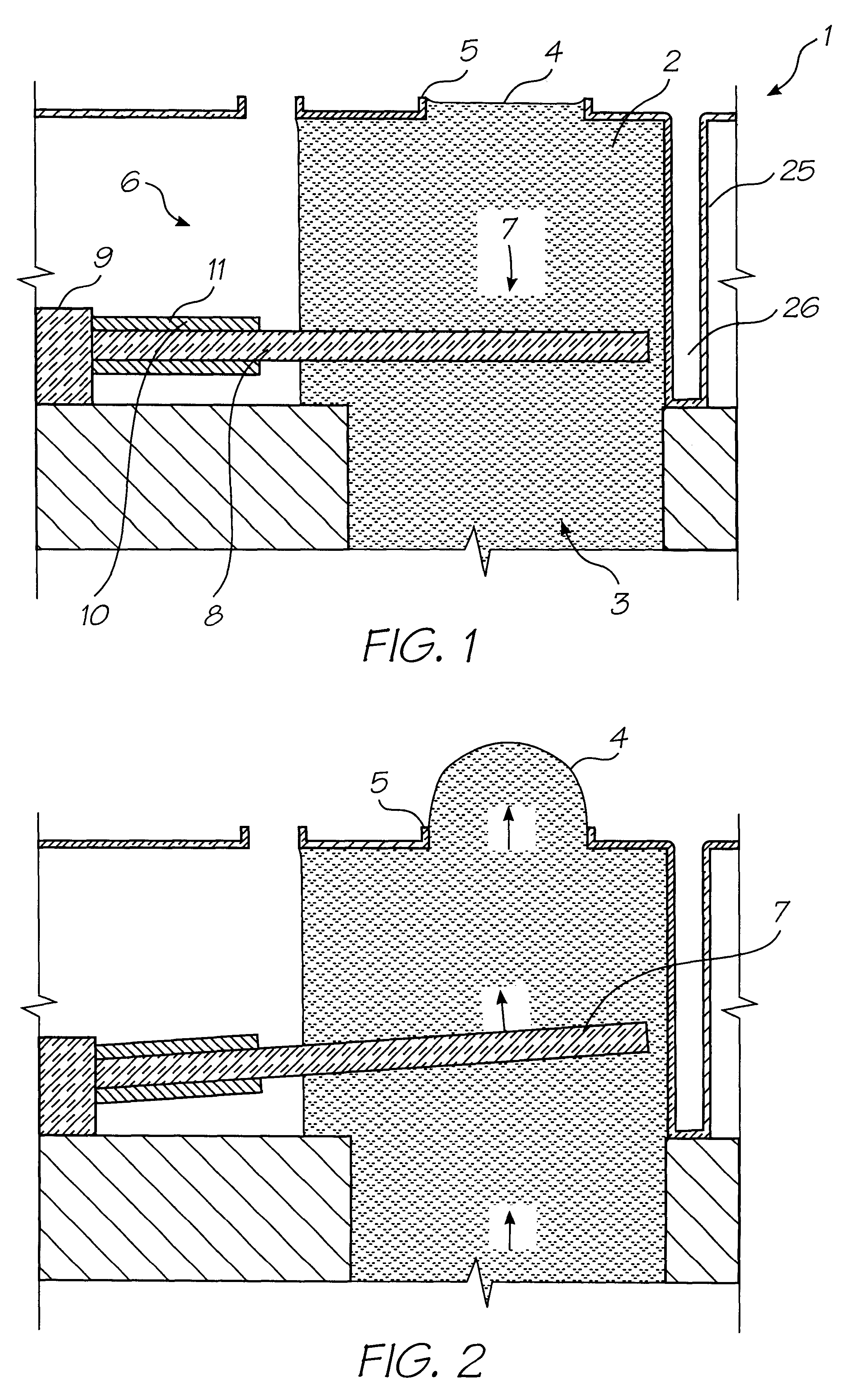
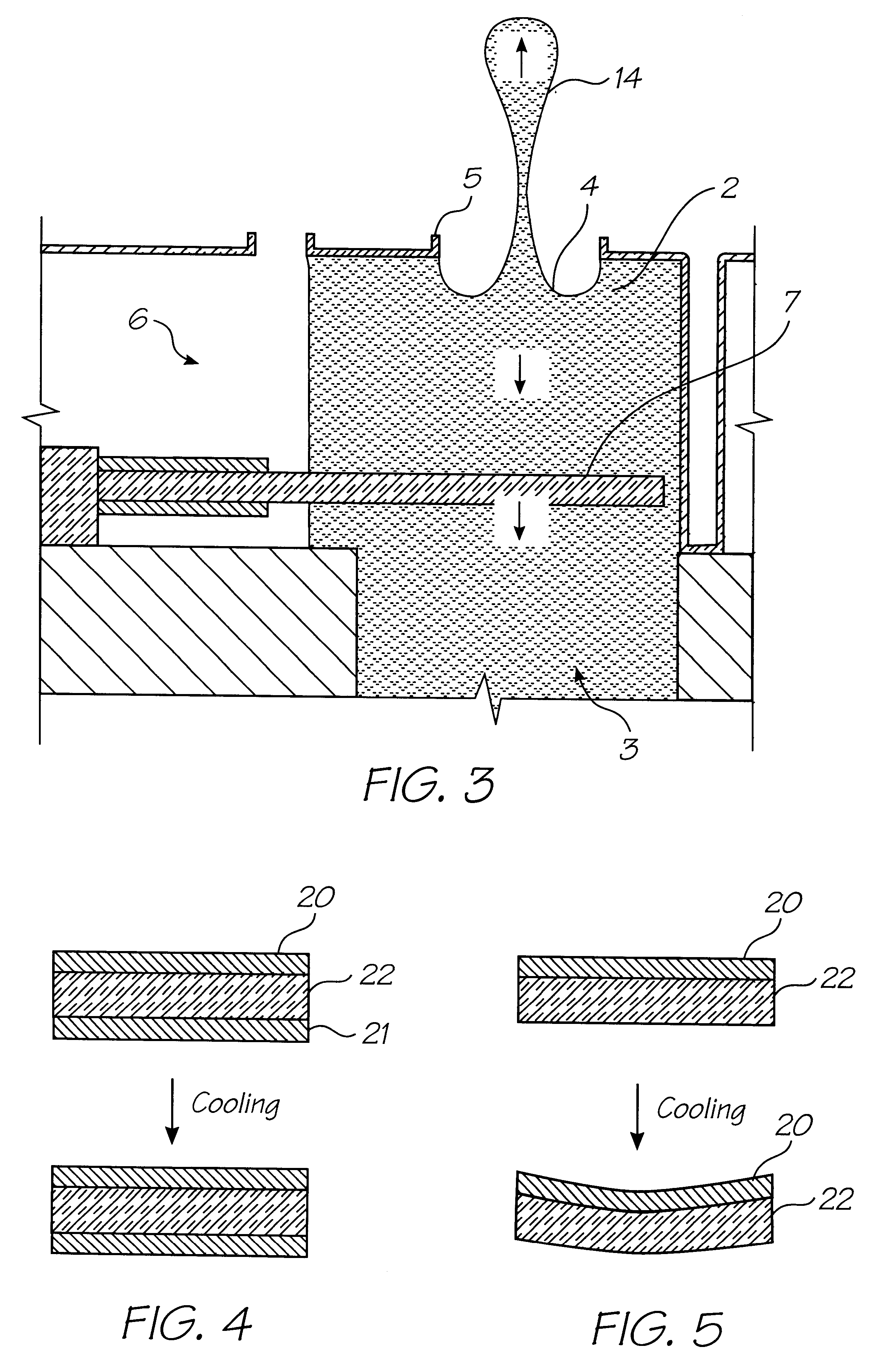
An ink jet printhead includes a number of nozzle devices formed on a substrate. Each nozzle device has a nozzle chamber, a nozzle opening through which ink from the nozzle chamber is ejected, a movable element in contact with ink in the nozzle chamber to cause the ejection of ink and thermal bend actuator. The thermal bend actuator has a proximal end anchored to the substrate and a distal end connected to the movable element. The actuator includes a first portion adjacent the proximal end and having a conducting heating circuit layer for heating the actuator. A second end portion of the actuator extends to the movable element and is in contact with ink in the chamber. A dielectric slot electrically isolates the first and second portions so that electric energy in the heating circuit layer is not conducted by the actuator to the ink in the chamber.

Description

The present invention relates to the construction of micro-electro mechanical devices such as inkjet printers and in particular discloses a process of electrical isolation of components from a fluid reservoir.CO-PENDING APPLICATIONSVarious methods, systems and apparatus relating to the present invention are disclosed in the following co-pending applications filed by the applicant or assignee of the present invention: 09 / 575,197 09 / 575,195 09 / 575,132 09 / 575,123 09 / 575,148 09 / 575,130 09 / 575,165 09 / 575,153 09 / 575,118 09 / 575,131 09 / 575,116 09 / 575,144 09 / 575,139 09 / 575,186 09 / 575,185 09 / 575,191 09 / 575,145 09 / 575,192 09 / 575,181 09 / 575,193 9 / 575,156 09 / 575,183 09 / 575,160 09 / 575,150 09 / 575,169 09 / 575,184 09 / 575,128 09 / 575,180 09 / 575,149 09 / 575,179 09 / 575,133 09 / 575,143 09 / 575,187 09 / 575,155 09 / 575,196 09 / 575,198 09 / 575,178 09 / 575,164 09 / 575,146 09 / 575,174 09 / 575,163 09 / 575,168 09 / 575,154 09 / 575,129 09 / 575,124 09 / 575,188 09 / 575,189 09 / 575,162 09 / 575,172 09 / 575,170 09 / 575,171 09 / 575,161 09 / 57...

Claims


Application Information

Patent Timeline
Patent Type & Authority Patents(United States)
IPC IPC(8): B41J2/05B41J2/14B41J2/16B41J2/045B41J2/055
CPCB41J2/04528B41J2/04553B41J2/04563B41J2/0457B41J2/04585B41J2/04588B41J2/0459B41J2/04591B41J2/04596B41J2/04598B41J2/14427B41J2/1623B41J2/1628B41J2/1629B41J2/1631B41J2/1632B41J2/1635B41J2/1637B41J2/1639B41J2/1642B41J2/1645B41J2/1646B41J2/1648B41J2002/14435B41J2002/14443B41J2/05
Inventor SILVERBROOK, KIA
Owner MEMJET TECH LTD
Learn More