Method of reducing space charge in a linear ion trap mass spectrometer

Inactive Publication Date: 2003-09-30
MDS CO LTD +2
View PDF9 Cites 39 Cited by
  • Summary
  • Abstract
  • Description
  • Claims
  • Application Information

AI Technical Summary

Problems solved by technology

Whenever this ion density increases above a particular limit, the resolution and mass assignment accuracy degrad

Method used


Image

  • Method of reducing space charge in a linear ion trap mass spectrometer
  • Method of reducing space charge in a linear ion trap mass spectrometer
  • Method of reducing space charge in a linear ion trap mass spectrometer

Examples


Embodiment Construction

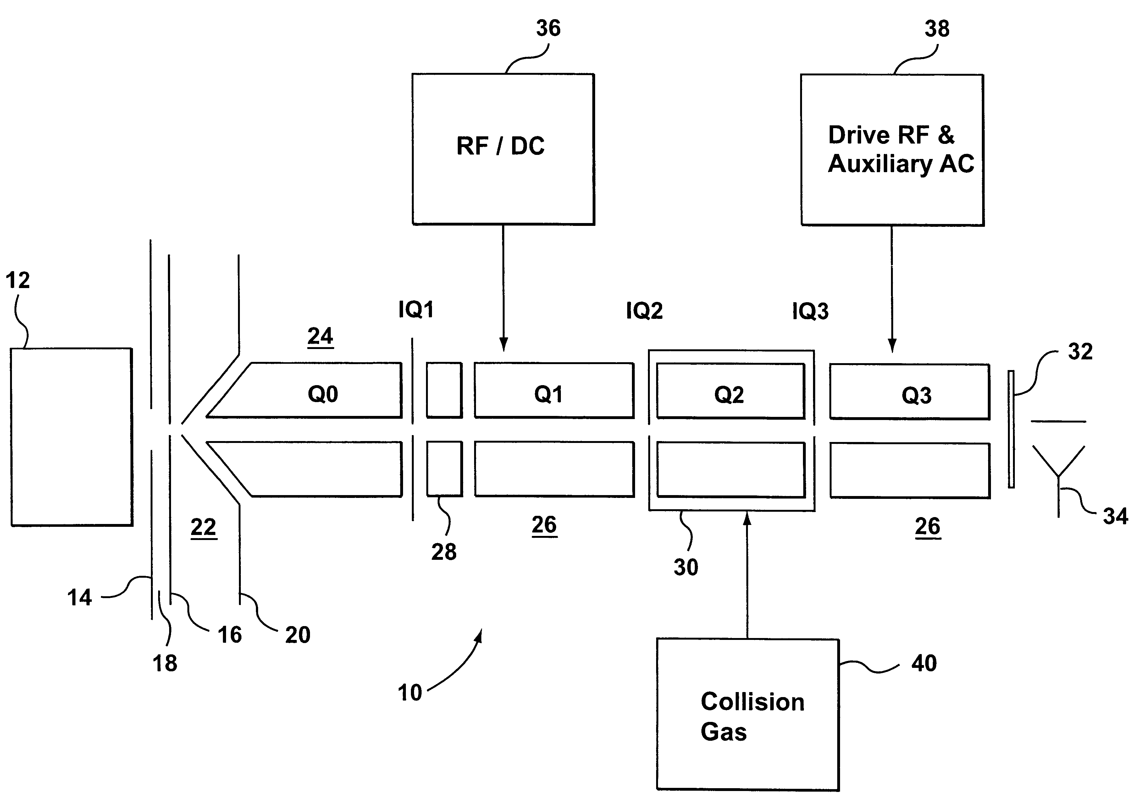
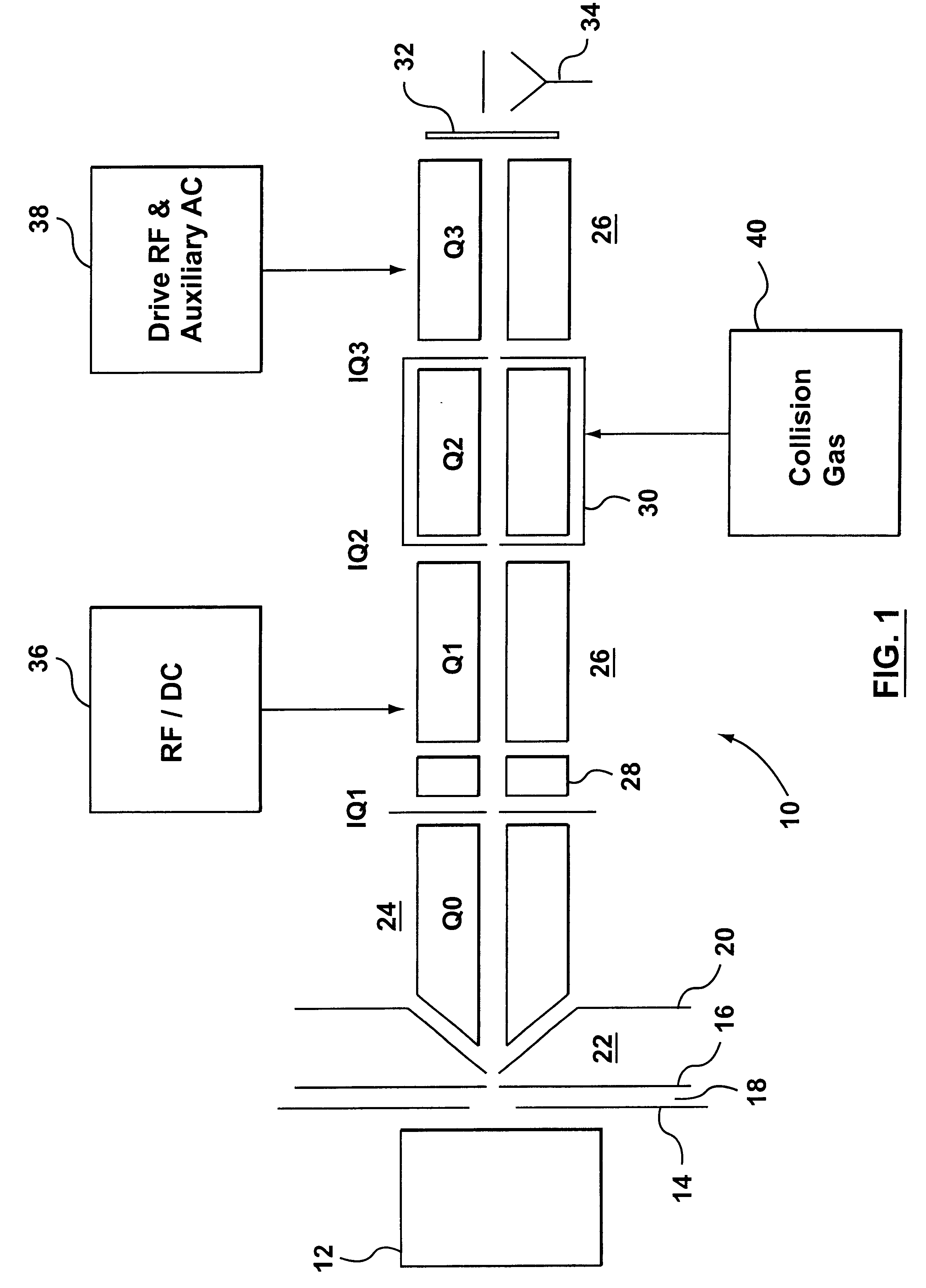
Referring first to FIG. 1, there is shown a conventional triple quadruple mass spectrometer apparatus generally designated by reference 10. An ion source 12, for example an electrospray ion source, generates ions directed towards a curtain plate 14. Behind the curtain plate 14, there is an orifice plate 16, defining an orifice, in known manner.

A curtain chamber 18 is formed between the curtain plate 14 and the orifice plate 16, and a flow of curtain gas reduces the flow of unwanted neutrals into the analyzing sections of the mass spectrometer.

Following the orifice plate 16, there is a skimmer plate 20. An intermediate pressure chamber 22 is defined between the orifice plate 16 and the skimmer plate 20 and the pressure in this chamber is typically of the order of 2 Torr.

Ions pass through the skimmer plate 20 into the first chamber of the mass spectrometer, indicated at 24. A quadruple rod set Q0 is provided in this chamber 24, for collecting and focusing ions. This chamber 24 serves ...


PUM


Abstract

A method of setting a fill time for a mass spectrometer including a linear ion is provided. The mass spectrometer is operated first in a transmission mode and ions are supplied to the mass spectrometer. Ions are detected as they pass through at least part of the mass spectrometer in a preset time period, to determine the ion current. From a desired maximum charge density for the ion trap and the ion current, a fill time for the ion trap is determined. The mass spectrometer is operated in a trapping mode to trap ions in the ion trap, and the ion trap is filled for the fill time, as just determined. This utilizes the ion trap to its maximum, while avoiding problems due to overfilling the trap, causing space charge effects.

Description

This invention relates to ion trap mass spectrometers and more particularly to controlling and reducing space charge effects in such mass spectrometers.Conventional ion trap mass spectrometers, of the kind described in U.S. Pat. No. 2,939,952, are generally composed of three electrodes, namely a ring electrode, and a pair of end cap electrodes. Appropriate applied RF and DC voltages are applied to the electrodes to establish a three dimensional field which traps ions within a specified mass-to-charge range. Linear quadruples can also be configured as ion trap mass spectrometers where radial confinement is provided by an applied RF voltage and axial confinement by DC barriers at the ends of the rod array. Mass selective detection of ions trapped within a linear ion trap can be accomplished by ejecting the ions radially, as taught by U.S. Pat. No. 5,420,425, or by ejecting the ions axially, as taught by U.S. Pat. No. 6,177,668. Ions may also be detected in situ using Fourier Transform...

Claims


Application Information

Patent Timeline
IPC IPC(8): H01J49/42H01J49/34H01J49/00G01N27/62
CPCH01J49/4225H01J49/424H01J49/4265H01J49/427Y10S430/143
Inventor HAGER, JAMES W.
Owner MDS CO LTD
Why Eureka
Try Eureka