
Light emitting body, light emitting element and light emitting display device using same

a technology of light emitting elements and light emitting bodies, applied in the direction of conductive layers on insulating supports, identification means, instruments, etc., can solve the problems of light emitting bodies or light emitting elements being susceptible to moisture, oxygen, and characteristic of conventional electrodes

Inactive Publication Date: 2003-09-30
SAMSUNG DISPLAY CO LTD
View PDF7 Cites 34 Cited by
  • Summary
  • Abstract
  • Description
  • Claims
  • Application Information

AI Technical Summary

Problems solved by technology

However, a fluorescent organic body used as a material for the light emitting layer in the conventional organic EL device used as the light emitting body or light emitting element is susceptible to moisture, oxygen, or a like.
Moreover, a characteristic of the conventional electrode (hereinafter being called a facing electrode) being placed directly on the light emitting layer or with a hole injecting layer or an electron injecting layer being interposed between the light emitting layer and the facing electrode is easily deteriorated by oxidation.
Because of this, when the conventional organic EL device is operated in the atmosphere, a characteristic of its light emission is rapidly deteriorated.
If oxygen or moisture exists in the vicinity of the conventional organic EL device, organic materials are deteriorated easily by oxidation which causes peeling of the film and growth of a dark spot (non-emitting portion) and, as a result, a phenomenon with which no light is emitted occurs.
This presents a problem in that a life of the organic EL device is shortened.
However, only by applying such the encapsulating technologies as described above, it is impossible to completely remove moisture and / or oxygen existing in the vicinity of an organic EL device.
As a result, it is difficult to secure a sufficient light emitting life of the conventional organic EL device.
Another problem is that, if such the conventional method of encapsulating technology is employed, an increase in a thickness of a display device itself using such the organic EL device is inevitable due to an additionally attached sealing material.
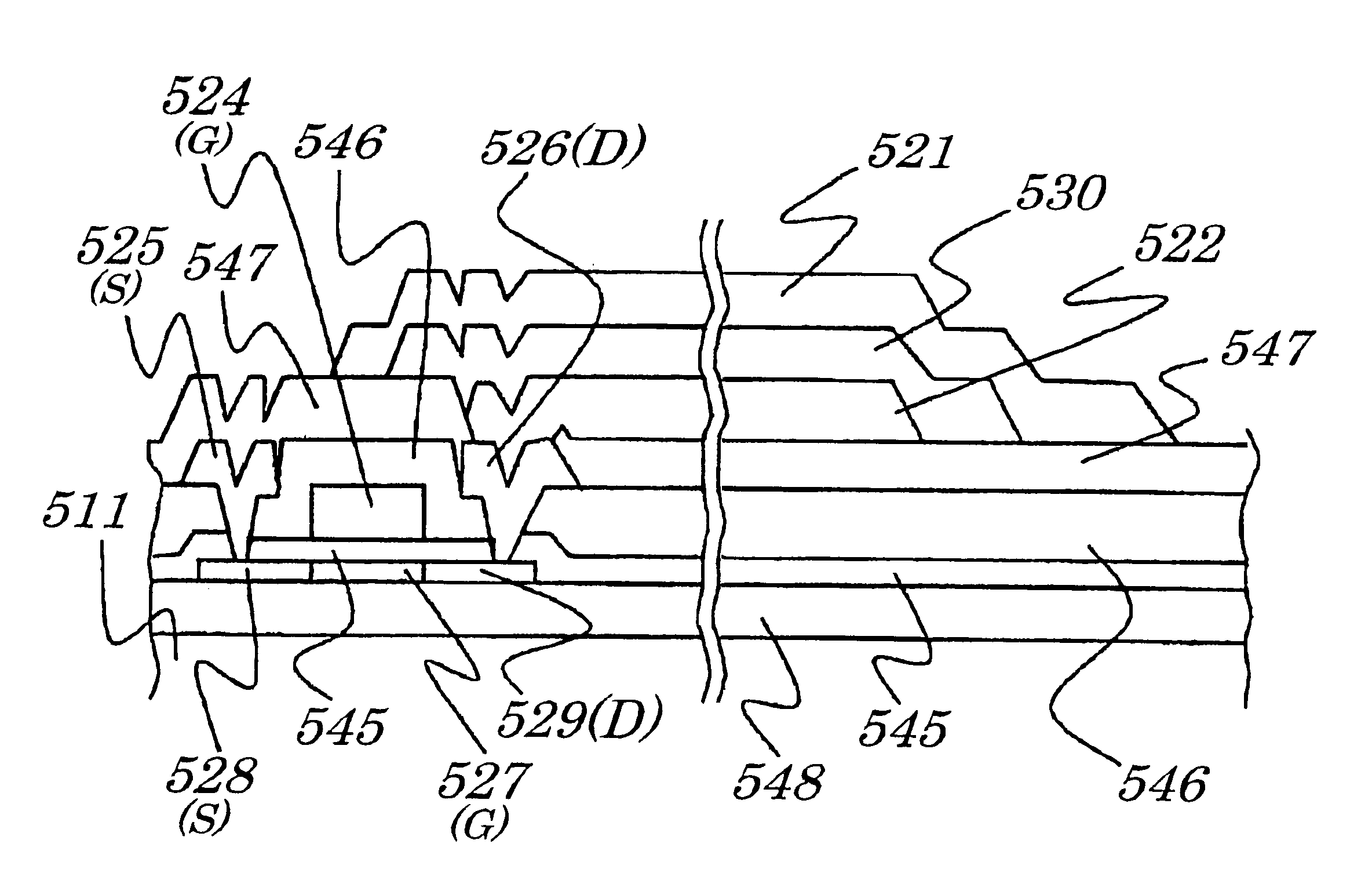
Though this portion is located far from the light emitting element portion and has no direct bearing on the light emission, peeling of the light emitting material layer 30b occurs due to corrosion in the portion and a light emission characteristic of the light emitting body 10b is adversely affected in some cases.
However, since a new process of forming the insulating layer 44c has to be added, its manufacturing costs increase accordingly.
However, since a new process of burying the insulating layer 44p has to be added, its manufacturing costs increase accordingly.
However, a new process of burying the insulating layer 44q has to be added and its manufacturing costs increase accordingly.

Method used


Image

  • Light emitting body, light emitting element and light emitting display device using same
  • Light emitting body, light emitting element and light emitting display device using same
  • Light emitting body, light emitting element and light emitting display device using same

Examples


Embodiment Construction

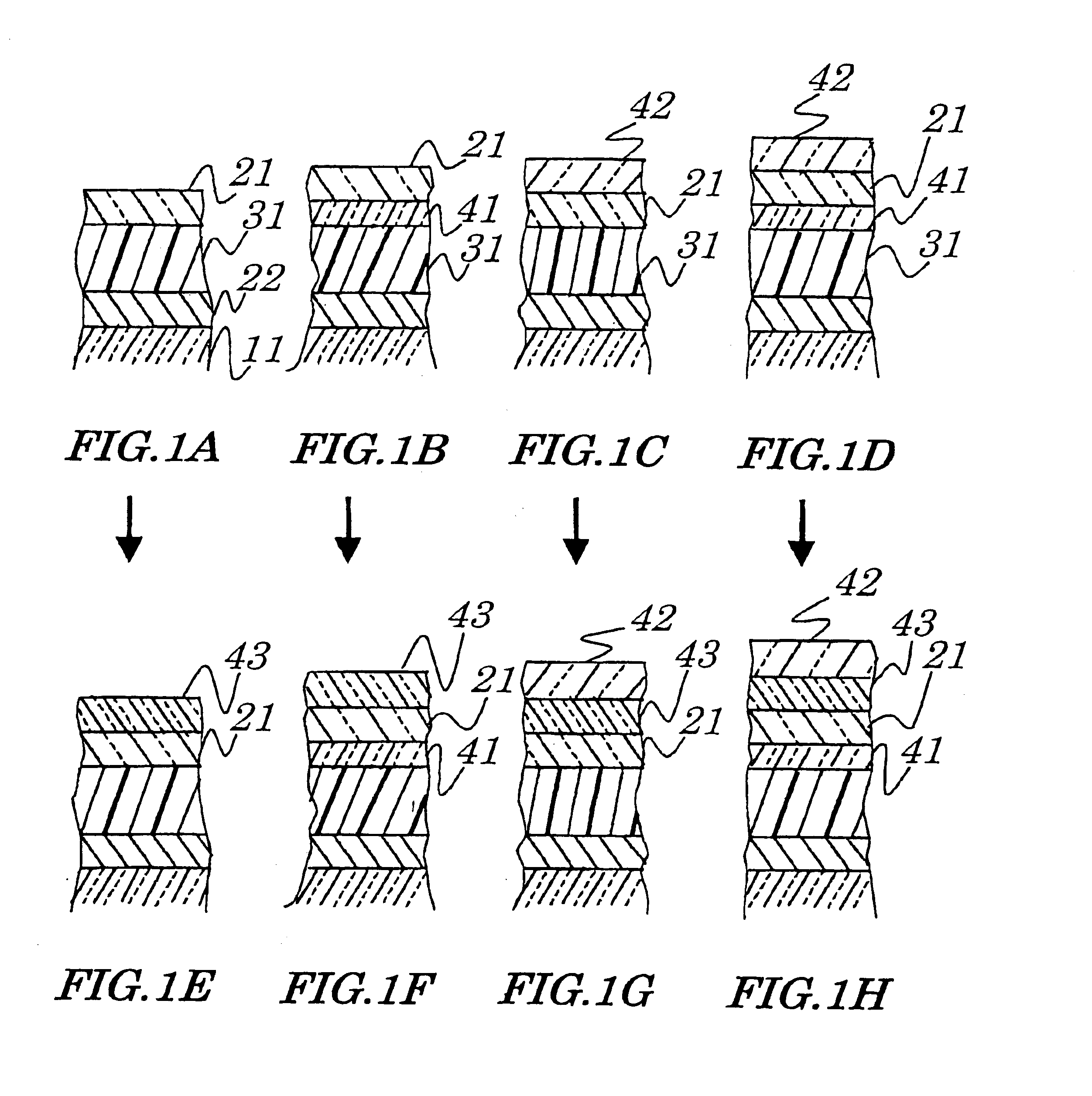
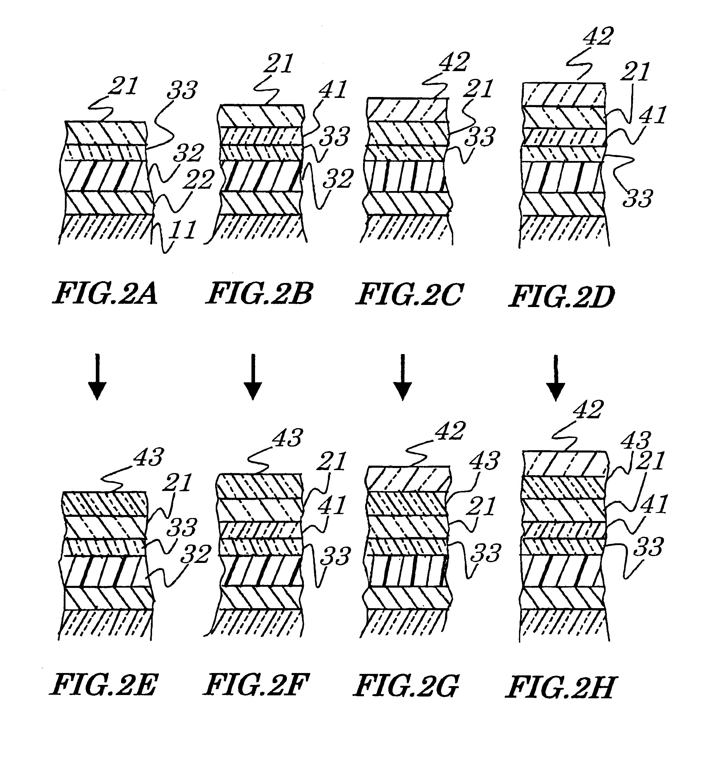
Results obtained by setting following conditions to a prototype of a light emitting display device using a light emitting element having configurations described below will be described. The light emitting body used in the prototype has the same layer structure as shown in FIG. 8D, that is, it is made up of the transparent electrode layer 21, anode buffer layer 41, hole injecting layer 33, light emitting layer 36 also serving as the electron transporting layer 35, upper electrode layer 23 and protecting layer 42 all being stacked in order on the substrate 11. Configurations of the light emitting body shown in FIGS. 18A to 18C are used here. Therefore, in this light emitting body, light is emitted downward to the substrate and a display is seen from a direction a lower side of the substrate 11 made up of the glass substrate upward an upper portion of stacked layers. The light emitting body is so constructed that, as shown in FIG. 27, the transparent electrode layer 21v is formed whic...


PUM

PropertyMeasurementUnit
temperatureaaaaaaaaaa
voltageaaaaaaaaaa

Abstract

An organic electroluminescence device is provided which is capable of providing light emission lasting time that can be practically used, that is, of improving its light emission life. A light emitting body used in the organic electroluminescence device is made up of a lower electrode layer, a light emitting layer and a transparent electrode layer being stacked in order on a substrate. As a material for the transparent electrode layer, a substance "In2-xSnxO3-y" being a mixture of an oxide of indium with tin is employed as its chief component. A material having hygroscopicity is formed adjacent to the transparent electrode layer. Light emitting element portion made up of the electrode and light emitting material layer is the electroluminescence device.

Description

1. Field of the InventionThe present invention relates to a light emitting body, light emitting element and light emitting display device using the same and more particularly to the light emitting body and light emitting element which can secure practical light emission lasting time and to the light emitting display device using the light emitting body and light emitting element.The present application claims priority of Japanese Patent Application No.2001-051410 filed on Feb. 27, 2001, which is hereby incorporated by reference.2. Description of the Related ArtGenerally, as a self-emitting body used for a display device, a field mission device and an electroluminescence (EL) device are available. The EL device can be classified into two types of devices, one being an organic EL device using an organic material as a light emitting layer and another being an inorganic EL device using an inorganic material as the light emitting layer.The organic EL device is generally made up of an ano...

Claims


Application Information

Patent Timeline
Patent Type & Authority Patents(United States)
IPC IPC(8): G09G3/32H01L51/52H01L51/50H05B33/26G09F9/30H01B5/14H01L27/32H05B33/04H05B33/12
CPCG09G3/3233H01L51/5206G09G2300/0842G09G2310/0262H01L51/5237H10K50/813H10K50/844H05B33/26H10K50/81H10K59/12
Inventor HAYASHI, KAZUHIKOFUKUCHI, TAKASHITSUBOI, SHINZOFUJIEDA, ICHIRO
Owner SAMSUNG DISPLAY CO LTD
Learn More