

Semiconductor device and method for manufacturing the same
a semiconductor and semiconductor technology, applied in the direction of transistors, electroluminescent light sources, electric lighting sources, etc., can solve the problems of significant resistance increase, signal delay due to wiring resistance, display unevenness, etc., to achieve high on/off ratio, small parasitic capacitance, and high electric characteristics
- Summary
- Abstract
- Description
- Claims
- Application Information
AI Technical Summary
Benefits of technology
Problems solved by technology
Method used
Image

Examples
embodiment 1
[0051]In this embodiment, a thin film transistor of a semiconductor device and a manufacturing process thereof will be described. Specifically, a manufacturing process of a pixel portion of a display device including a thin film transistor will be described.
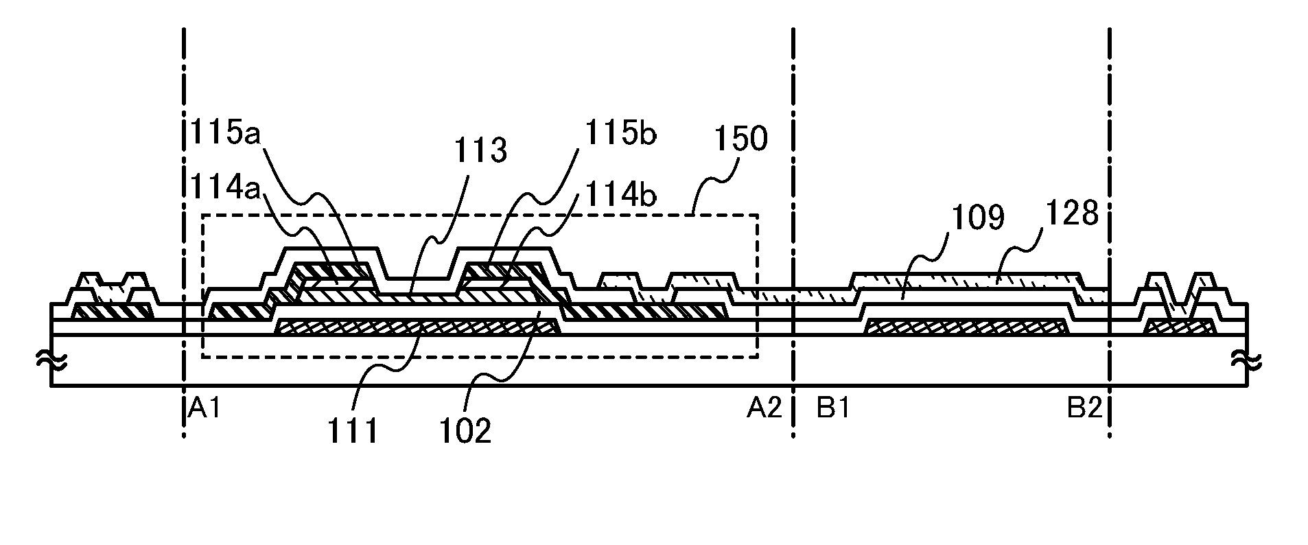
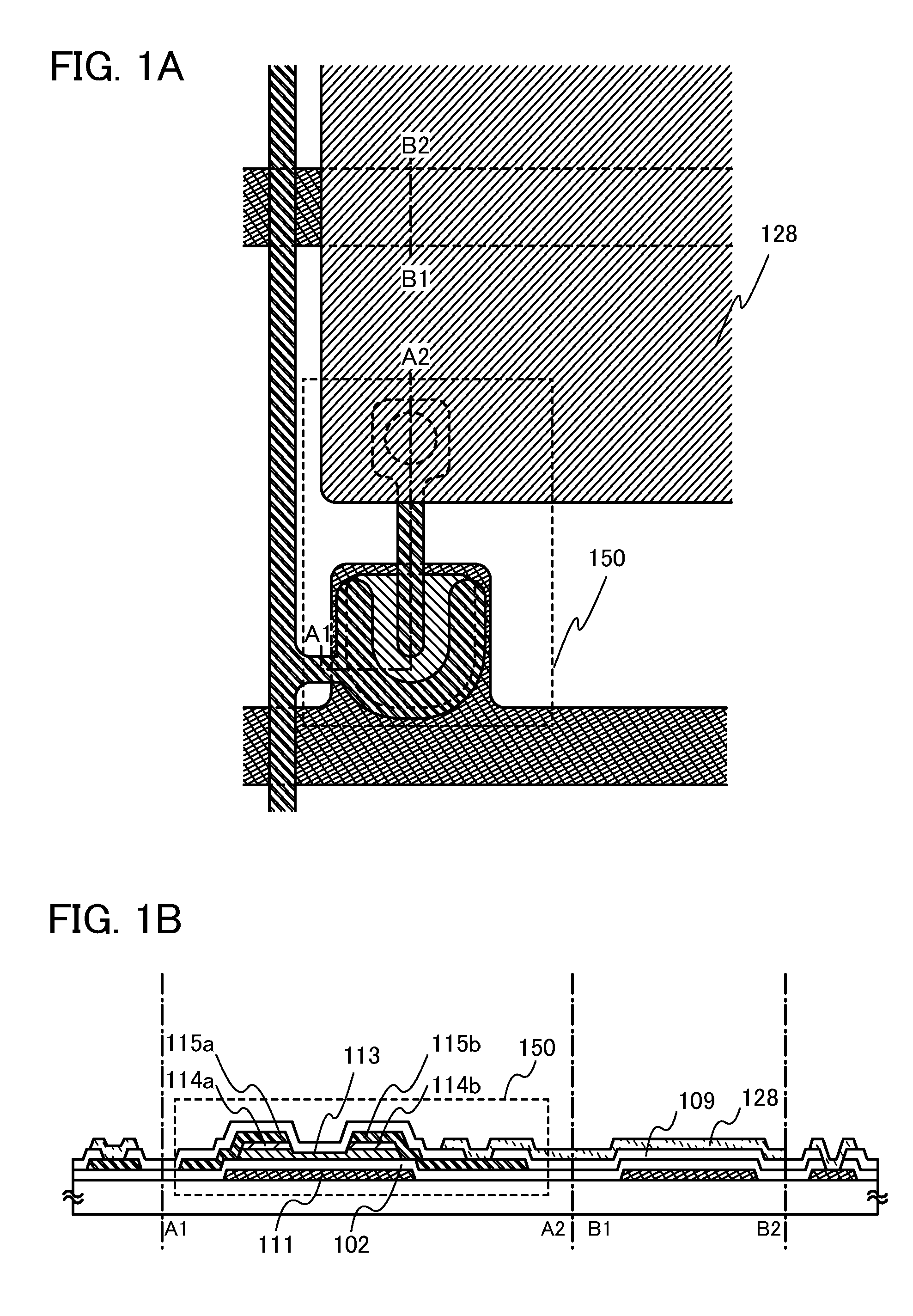
[0052]FIGS. 1A and 1B illustrate a thin film transistor of this embodiment. FIG. 1A is a top view and FIG. 1B is a cross-sectional view taken along line A1-A2 and line B1-B2 of FIG. 1A.
[0053]An oxide semiconductor layer 113 of a thin film transistor 150 illustrated in FIGS. 1A and 1B is provided under a first electrode 115a and a second electrode 115b which face with each other, thereby covering a gate electrode 111 with a gate insulating film interposed therebetween. That is, the oxide semiconductor layer 113 is provided so as to overlap with the gate electrode 111 and be in contact with a top surface of the gate insulating film 102 and bottom surfaces of buffer layers (114a and 114b). Here, the buffer layer 114a is provided bet...
embodiment 2
[0097]In this embodiment, a thin film transistor of a semiconductor device and a manufacturing process thereof will be described. Specifically, a manufacturing process of a pixel portion of a display device including a thin film transistor will be described.
[0098]FIGS. 4A and 4B illustrate a thin film transistor of this embodiment. FIG. 4A is a plan view and FIG. 4B is a cross-sectional view taken along line A1-A2 and line B1 and B2 of FIG. 4A.
[0099]In a thin film transistor 151 illustrated in FIGS. 4A and 4B, a gate electrode 111 is formed over a substrate 100; a gate insulating film 102 is formed over the gate electrode 111; a first electrode 115a and a second electrode 115b which are to be a source and drain electrodes are formed over the gate insulating film 102 so that an end portion of the first electrode 115a and an end portion of the second electrode 115b overlap with the gate electrode 111. The oxide semiconductor layer 113 is provided so as to overlap with the gate electro...
embodiment 3
[0124]Here, an example in which an inverter circuit is formed using two n-channel thin film transistors which are formed in a manner similar to that of Embodiment 2 will be described below as an embodiment of the present invention.
[0125]A driver circuit for driving a pixel portion is formed using an inverter circuit, a capacitor, a resistor, and the like. When two n-channel TFTs are combined to form an inverter circuit, there are two types of combinations: a combination of an enhancement type transistor and a depression type transistor (hereinafter, a circuit formed by such a combination is referred to as an “EDMOS circuit”) and a combination of enhancement type TFTs (hereinafter, a circuit formed by such a combination is referred to as an “EEMOS circuit”). Note that when the threshold voltage of the n-channel TFT is positive, the n-channel TFT is defined as an enhancement type transistor, while when the threshold voltage of the n-channel TFT is negative, the n-channel TFT is define...
PUM
| Property | Measurement | Unit |
|---|---|---|
| Semiconductor properties | aaaaa | aaaaa |
Abstract
Description
Claims
Application Information