Substrate for magnetic recording medium, manufacturing method thereof, and magnetic recording medium

a technology of magnetic recording medium and manufacturing method, which is applied in the direction of magnetic materials for record carriers, manufacturing tools, instruments, etc., can solve the problems of high revolution speed of a substrate, affecting the quality of the product, so as to improve the machine characteristics and increase the surface roughness accuracy

Inactive Publication Date: 2003-10-14
FUJI ELECTRIC CO LTD
View PDF2 Cites 17 Cited by
  • Summary
  • Abstract
  • Description
  • Claims
  • Application Information

AI Technical Summary

Benefits of technology

It is an object of the present invention to provide a non-magnetic substrate with increased surface roughness accuracy and improved machine characteristics.
Another object of the present invention is to provide a process for manufacturing a substrate with reduced manufacturing cost.
A first surface treatment consists of pressing a running matrix in contact with part of a side of a revolving presubstrate at contact rates of 15 to 25 percent by area of the side and pressures of 20 g / cm.sup.2 to 150 g / cm.sup.2. This treatment smooths and roughens the presubstrate side appropriately in a single process. The treatment efficiently removes all of the irregularities from the substrate side, for instance, pits or nodules, etc. formed during plating a non-magnetic metal presubstrate. The treatment also avoids the clogging or deterioration of a pad incurred in a polishing process. Accordingly, the treatment provides, accurately and continuously, a side with an uniform and ultrafine surface conformation. The treatment also textures the presubstrate side simultaneously in the circumferential direction. Hence, the surface treatment performs both polishing and texturing at a time. This provides a simplified manufacturing process and a reduced manufacturing cost of a non-magnetic metal substrate. Contact rates of less than 15 percent make it difficult to remove all the irregularities of a presubstrate side in a single process. Contact rates of more than 25 percent cause such problems as clogging up and deterioration of a matrix. When pressures per unit area applied to a side of a presubstrate through a matrix are less than 20 g / cm.sup.2, the side is neither polished nor roughened sufficiently in one processing due to their poor processing ability. Pressures of more than 150 g / cm.sup.2 cause irregularities attributable to abrasive particles in abrasive suspension. Further, substrates can be manufactured with the present treatment one sheet after another. Combining the treatment with washing a presubstrate sheet one after another, and then sequentially forming a non-magnetic under layer, a magnetic layer, and a protective layer on the substrate by sputtering enables manufacture of a medium with no breaks in processing. This eliminates the adherence of foreign bodies to the in-process substrates during downtime. This provides a medium with an improved error characteristic compared to one made with downtime that permits adherence of foreign bodies to occur.
The first or a second surface treatments set forth earlier can be used for a non-magnetic glass presubstrate. In place of lapping and polishing, followed by chemical strengthening, the present invention easily mirror-finishes a side of a presubstrate. In addition, chemical strengthening a non-magnetic glass presubstrate, then, instead of polishing, performing either the first or second surface treatment set forth earlier, suppresses alkaline ions from leaching out of the strained layer at the surface of the presubstrate. Irregularities formed during chemical strengthening are removed with the treatment. Hence, the treatment of the present invention yields an excellent substrate side with no loss of substrate strength. A second surface treatment, preceded by the chemical strengthening, forms a minute texture in the circumferential direction of a presubstrate without changing the smoothness of the presubstrate side. A medium using the substrate made with the invention reduces stiction of a magnetic head to the surface of the medium. The term stiction is an acronym derived from STatic frICTION. Stiction is defined as friction that tends to prevent relative motion between relatively movable parts at their null position. Stiction is more commonly understood to be the periodic cyclical momentary adhesion of one surface to another. It is the phenomenon of stiction which vibrates a string of a bowed stringed instrument, and also produces the squeaking of a rusty door hinge.
In the case of a glass presubstrate, before polishing with a surface-treating machine as shown in FIG. 1, the surface is lapped and chemically chemical strengthened to provide a more uniform and smooth side of the presubstrate. Then the side of the presubstrate is polished with the machine shown in FIG. 1 to remove surface irregularities caused by the chemical strengthening process. In addition, this treatment reduces the alkaline component leached out onto the surface of the presubstrate side, thereby eliminating the loss of substrate properties.
A second surface treatment of a glass presubstrate, following chemical strengthening, with a machine shown in FIG. 1 provides a substrate with a texture in the circumferential direction of the substrate with no loss in smoothness of a substrate side. A medium made from the substrate has a reduction tendency for stiction between a magnetic head.

Problems solved by technology

The desired high revolution speed of a substrate gives rise to substrate oscillation, etc.
Polishing in the manufacture of a chemically strengthened glass substrate poses the problem that the polishing pad clogs up and deteriorates the same as in the manufacture of a non-magnetic metal substrate.
In addition, chemical strengthening following the polishing process leaves occasional surface irregularities (irregular projections).
On the other hand, polishing has the disadvantage that it causes deterioration and clogging of the pad during processing.
This makes it difficult to continuously produce uniform smoothness on the sides of the substrates.
Cleaning the pad, however, does not eliminate deterioration of the pad.
As a consequence, manufacturing cost is increased.
Polishing cannot form suitable grooves in the circumferential direction of the substrate corresponding to those produced in a texturing process.
Therefore, texturing is unsuitable for removing surface defects such as pits and nodules, etc. generated by plating.
Texturing, further, has the problem that pressure per unit area applied to the substrate cannot be reduced.
Increasing pressure per unit area applied to a substrate causes grit in the abrasive slurry increase its abrasive activity.
This increases the difficulty in forming a smooth side due to roughening of the surface and generation of blemishes such as scratches, etc.
However, as described above, texturing is no substitute for polishing in terms of forming a smooth and mirror finished side.

Method used


Image

  • Substrate for magnetic recording medium, manufacturing method thereof, and magnetic recording medium
  • Substrate for magnetic recording medium, manufacturing method thereof, and magnetic recording medium
  • Substrate for magnetic recording medium, manufacturing method thereof, and magnetic recording medium

Examples


example 2

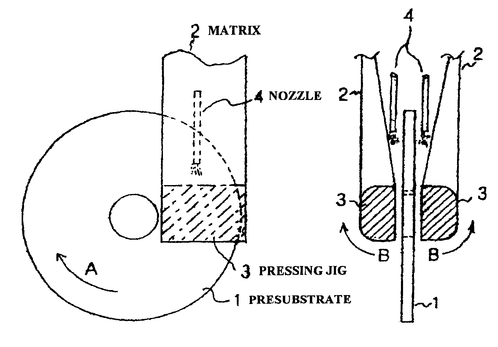
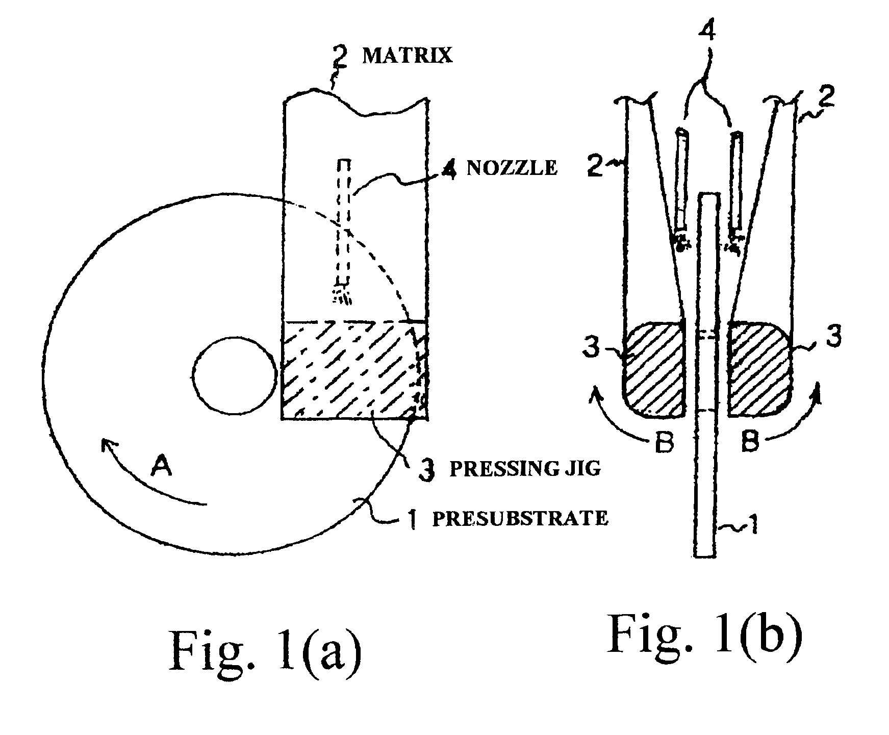
A side of 2.5-inch glass disk was lapped. Then, the side was mirror-finished with the machine shown in FIG. 1. An abrasive tape, which consisted of a urethane-foam pad, was used. The abrasive suspension was cerium oxide abrasive powder mixed with water at a concentration of 1 percent by weight. The abrasive powder had an average diameter of 1.5 {character pullout}m. The abrasive tape was pressed in contact with part of a side of a revolving disk contacting 20 percent of the area of the side and with a pressure of 62.5 g / cm.sup.2. The disk revolved at a rate of 200 rpm. The glass disk had a center line average height Ra of 0.5 nm after the treatment, in contrast to its center line average height Ra of 15 nm before the treatment.

example 3

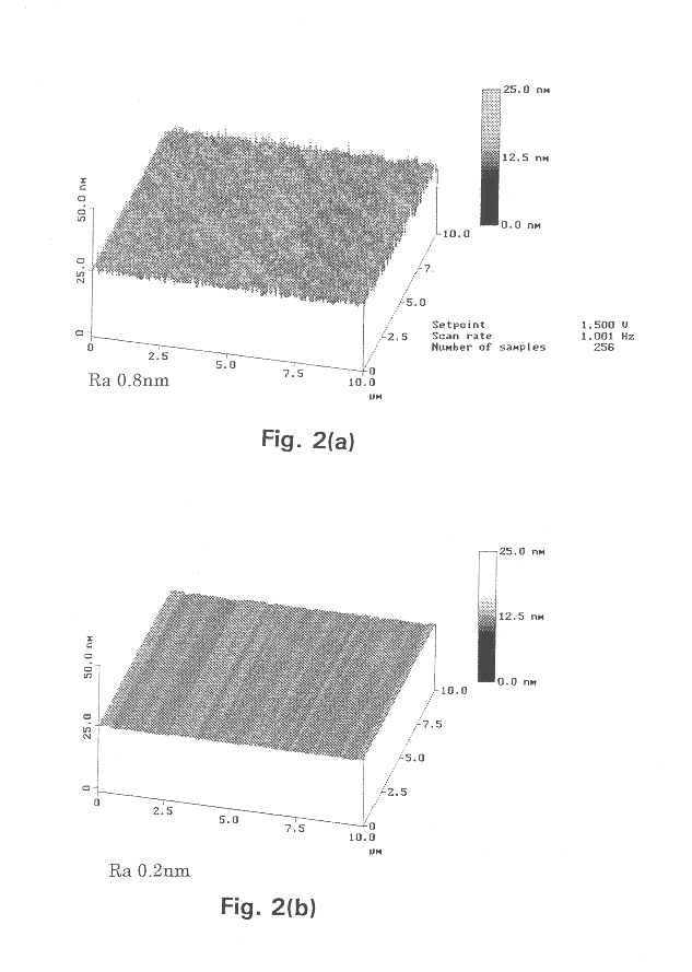
The side of a 2.5-inch glass disk was lapped. The first step of polishing was applied to the side, instead of the usual two-step polishing, followed by chemical strengthening. Then, the side was treated with a machine shown in FIG. 1. An abrasive tape, which consisted of a urethane-foam pad, was used. The abrasive suspension was cerium oxide abrasive powder mixed with water at a concentration of 1 percent by weight. The abrasive powder had an average diameter of 1.5 {character pullout}m. The abrasive tape was pressed in contact with part of a side of a revolving disk contacting 20 percent by area of the side and with a pressure of 40 g / cm.sup.2. The disk revolved at a rate of 200 rpm.

The surface roughness of a glass disk side was examined and evaluated before and after the treatment with an atomic force microscope (AFM). The glass disk had center line average height Ra of 0.2 nm after the treatment, compared to its center line average height Ra of 0.8 nm before the treatment.

FIG. 2(...

example 4

The side of a 2.5-inch glass disk was lapped, polished in two steps, and chemically strengthened conventionally. The glass disk was textured in the circumferential direction with the machine shown in FIG. 1 to prevent stiction between a magnetic head and the recording medium. An abrasive tape, which consisted of a urethane-foam pad, was used. The abrasive suspension was cerium oxide abrasive powder mixed with water at a concentration of 1 percent by weight. The abrasive powder had an average diameter of 1.5 {character pullout}m. The abrasive tape was pressed in contact with part of a side of a revolving disk at a contact rate of 4 percent by area of the side and at a pressure of 440 g / cm.sup.2. The disk revolved at a rate of 100 rpm.

The glass disk had center line average height Ra of 0.5 nm before and after the treatment. The surface of the glass disk, however, was textured in the circumferential direction with maximum height Rmax of approximately 7 nm. Change in an alkaline content...


PUM

PropertyMeasurementUnit
diameteraaaaaaaaaa
height Raaaaaaaaaaa
height Raaaaaaaaaaa

Abstract

A slowly advancing tape-shaped matrix is pressed into contact with a surface of a rapidly rotating non-magnetic substrate for a magnetic recording medium. An abrasive slurry is added to the matrix. The area contact rate between the matrix and the surface, as well as the contact pressure per unit area between the matrix and the surface are regulated to both polish and slightly roughen the surface in a single process. In the case of a glass presubstrate, the glass is chemically strengthened before being surface-treated.< / PTEXT>

Description

1. Field of the InventionThe present invention relates to a non-magnetic substrate used for a magnetic recording medium to be mounted in various magnetic recording devices such as the external memories of computers. The present invention also relates to a manufacturing method for the substrate, and a magnetic recording medium incorporating the substrate.2. Prior ArtA substrate for a magnetic recording medium (hereinafter simply referred to as a medium), for high recording density, requires highly accurate surface roughness and mechanical properties. These properties are attained by highly developed precision processing and polishing. Demand for a substrate with higher accuracy surface roughness and mechanical properties comes from the necessity for a magnetic head to fly at a lower flying height over the magnetic medium. As the recording density increases, the flying height must be further reduced.Aluminum alloy, etc. has chiefly been employed for the substrate for the medium. A cir...

Claims


Application Information

Patent Timeline
Patent Type & Authority Patents(United States)
IPC IPC(8): G11B5/84B24B21/00B24B21/08
CPCG11B5/8404Y10S428/90
Inventor SHIMADA, TAKASHI
Owner FUJI ELECTRIC CO LTD
Why Eureka
Try Eureka