
Interleaver-deinterleaver megacore

Inactive Publication Date: 2003-10-14
ALTERA CORP
View PDF11 Cites 50 Cited by
  • Summary
  • Abstract
  • Description
  • Claims
  • Application Information

AI Technical Summary

Benefits of technology

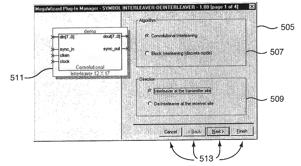
FIG. 3B is a table showing a variety of signals that can be used in designin

Problems solved by technology

When an integrated circuit manufacturer supplies a typical programmable logic device, it is not yet capable of performing any specific function.

Method used


Image

  • Interleaver-deinterleaver megacore
  • Interleaver-deinterleaver megacore
  • Interleaver-deinterleaver megacore

Examples


Embodiment Construction

will be with reference to one or more preferred embodiments of the invention, but is not limited to such embodiments. The detailed description is intended only to be illustrative. Those skilled in the art will readily appreciate that the detailed description given herein with respect to the FIGURES is provided for explanatory purposes as the invention extends beyond these limited embodiments. For example, the present invention is described in connection with a variety of exemplary interleaver / de-interleaver variable parameters. However, the present invention may incorporate and use other parameters and variable values in parameterizing and optimizing an interleaver and / or de-interleaver function(s).

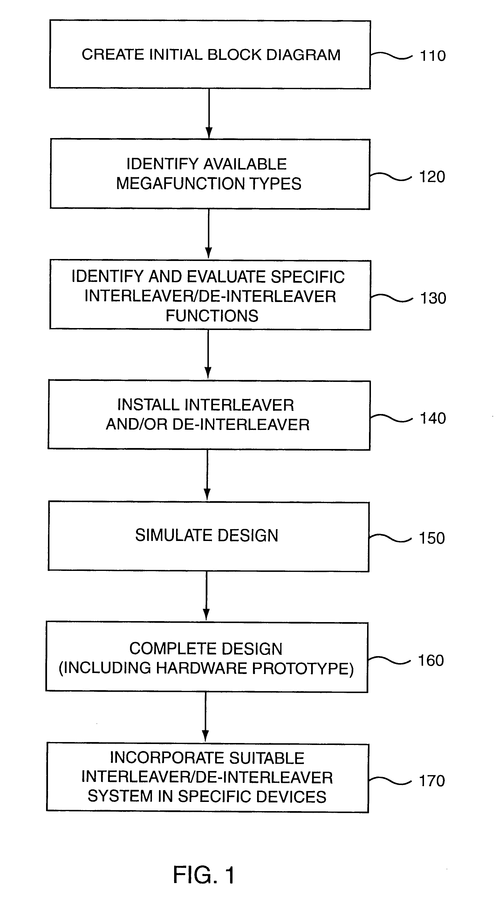
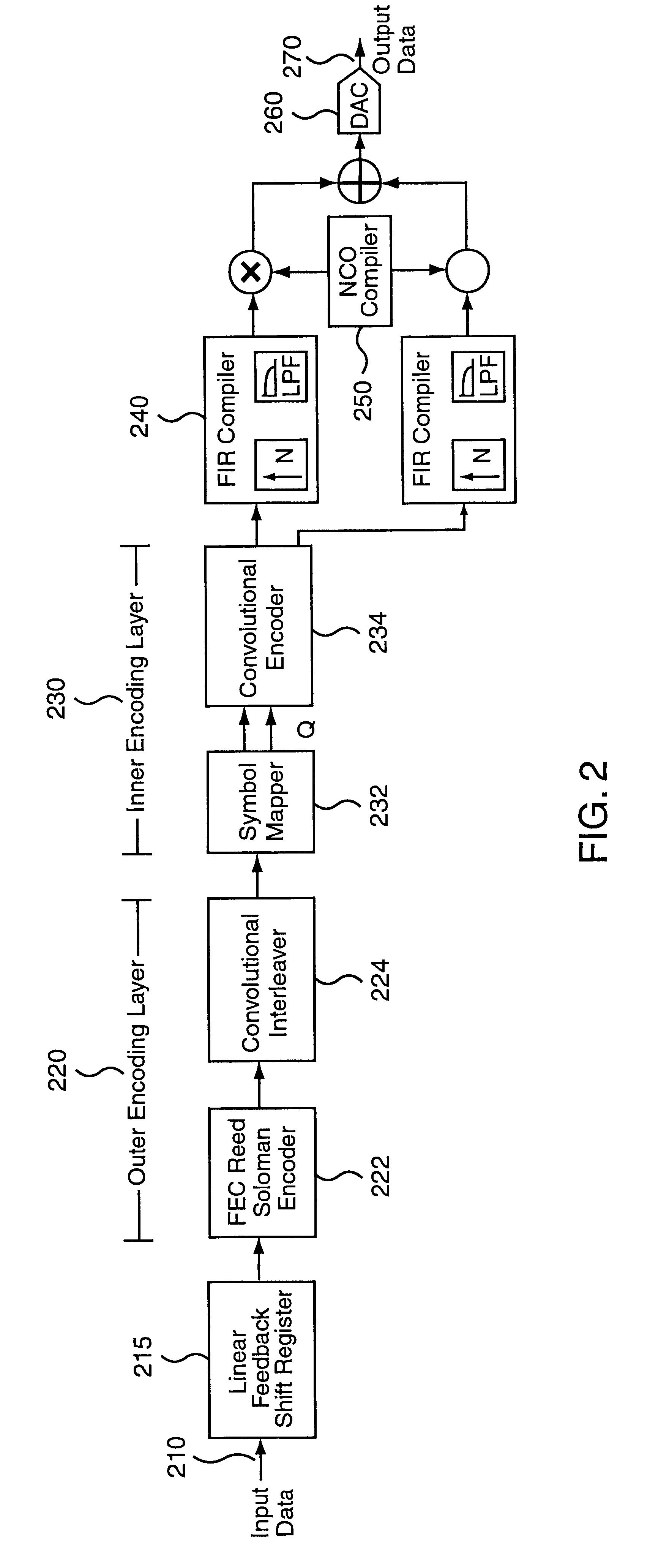
The present invention provides methods and apparatuses for creating a parameterized and optimized interleaver / de-interleaver megafunction for use in an electronic design, where the interleaver / de-interleaver megafunction requires specific setting of at least one variable parameter value. ...


PUM


Abstract

Methods and apparatuses are disclosed for creating a parameterized interleaver / de-interleaver megafunction for use in an electronic design, where the interleaver / de-interleaver megafunction requires specific setting of at least one variable parameter value. The method includes presenting a user with the opportunity to specify an adjustable parameter value for at least one interleaver / de-interleaver parameter. The specified parameter value then is received and a suitable interleaver and / or de-interleaver system is generated.< / PTEXT>

Description

1. Field of the InventionThis invention relates generally to methods, machine readable media and apparatuses for digital systems. In particular, the present invention relates to communication and transmission of digital data and electronic designs relating thereto.2. Description of Related ArtA programmable logic device (PLD) is a programmable integrated circuit that allows the user of the circuit, using software control, to program particular logic functions the circuit will perform. A wide variety of these devices are manufactured by Altera Corporation. A more complete description of these types of devices and their uses can be found at "www.altera.com" and in various materials published by Altera, but the basic structure and operation of PLDs are well known to those of ordinary skill in the art. Logic functions performed by small, medium, and large-scale integration integrated circuits can instead be performed by programmable logic devices. When an integrated circuit manufacturer...

Claims


Application Information

Patent Timeline
IPC IPC(8): G06F17/50
CPCH03M13/2732G06F17/5045G06F30/30
Inventor MOLSON, PHILIPPESAN, TONY
Owner ALTERA CORP
Learn More