Direct venting vent pipe

a vent pipe and vent pipe technology, applied in the field of chimney pipes, can solve the problems of cumbersome connection of pipe sections in some pipe assemblies, inability to meet the needs of sufficient insulation of vent pipes, and inability to achieve the effect of facilitating pipe runs of unrestricted length

Inactive Publication Date: 2003-10-21
CARDINAL IP HLDG LLC
View PDF8 Cites 28 Cited by
  • Summary
  • Abstract
  • Description
  • Claims
  • Application Information

AI Technical Summary

Benefits of technology

The present invention overcomes the disadvantages of the prior known vent pipe assemblies by providing a pipe constructed of sections lockingly and sealingly connected to facilitate pipe runs of unrestricted length.
The direct venting pipe includes a double wall system which allows for the flow of exhaust gases created from the combustion of gaseous hydrocarbons such as natural gas, wood products or propane from the appliance. The pipe allows simultaneous flow of oxygenated air from a suitable source to mix with the gaseous hydrocarbons for more efficient combustion. The piping system incorporates tubes formed of galvanized and stainless sheet metal to create a concentric pipe capable of containing such exhaust or oxygenated gases at elevated or lowered temperatures without leakage through the seams of the joined pipe sections. The pipe sections are sealed by the unique application of an O-ring seal mounted to the pipe ends to prevent any leakage and mixing of the gases. The pipe joints are further joined by a locking system incorporated into the exterior wall which joins the pipe sections longitudinally. The locking system also serves as an integral part of the sealing system by ensuring sealing seating of the O-ring seals.
The present invention further incorporates termination caps for both horizontal and vertical installations. The termination caps maintain separation of the exhaust and oxygenated air during use. Such caps further serve to repel precipitation and objects from entering the pipe system and are attached to the pipe segments utilizing the unique sealing and locking mechanisms of the present invention.

Problems solved by technology

Furthermore, such vent pipes can become hot requiring sufficient insulation around building materials.
However, connection of the pipe sections in some pipe assemblies is cumbersome requiring fasteners and the like.

Method used


Image

  • Direct venting vent pipe
  • Direct venting vent pipe
  • Direct venting vent pipe

Examples


Embodiment Construction

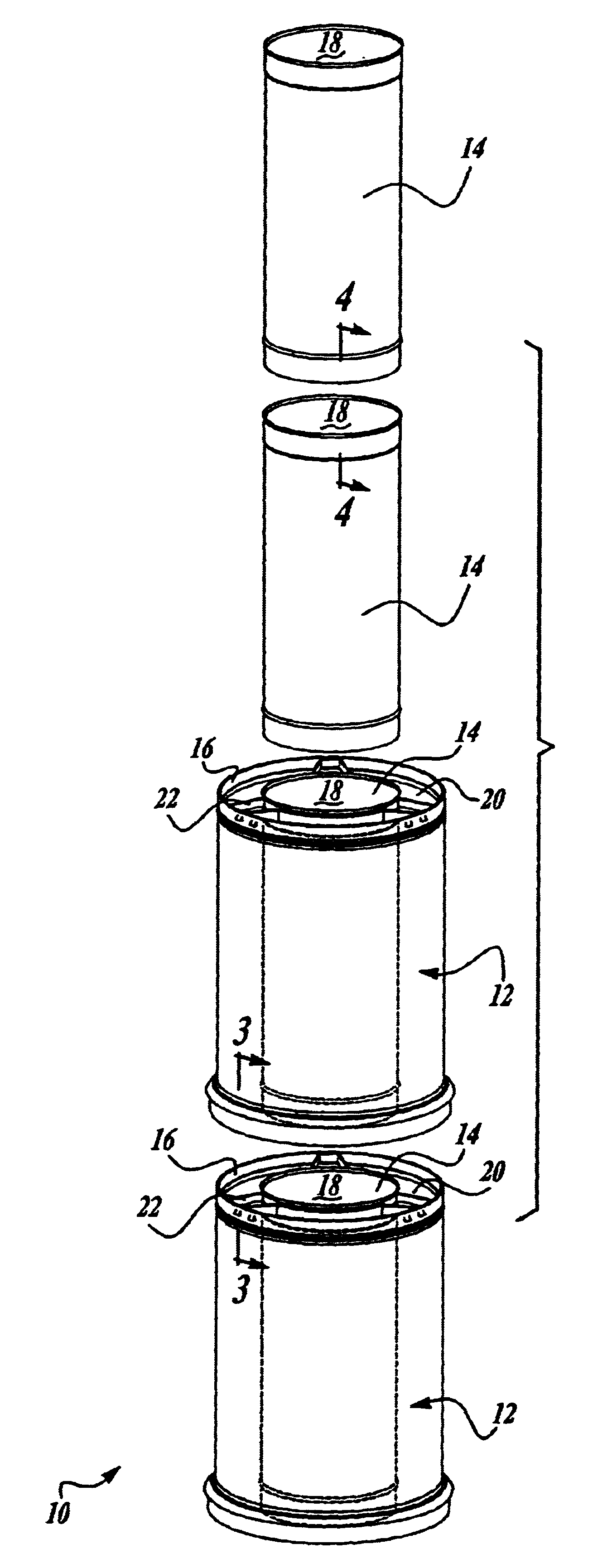
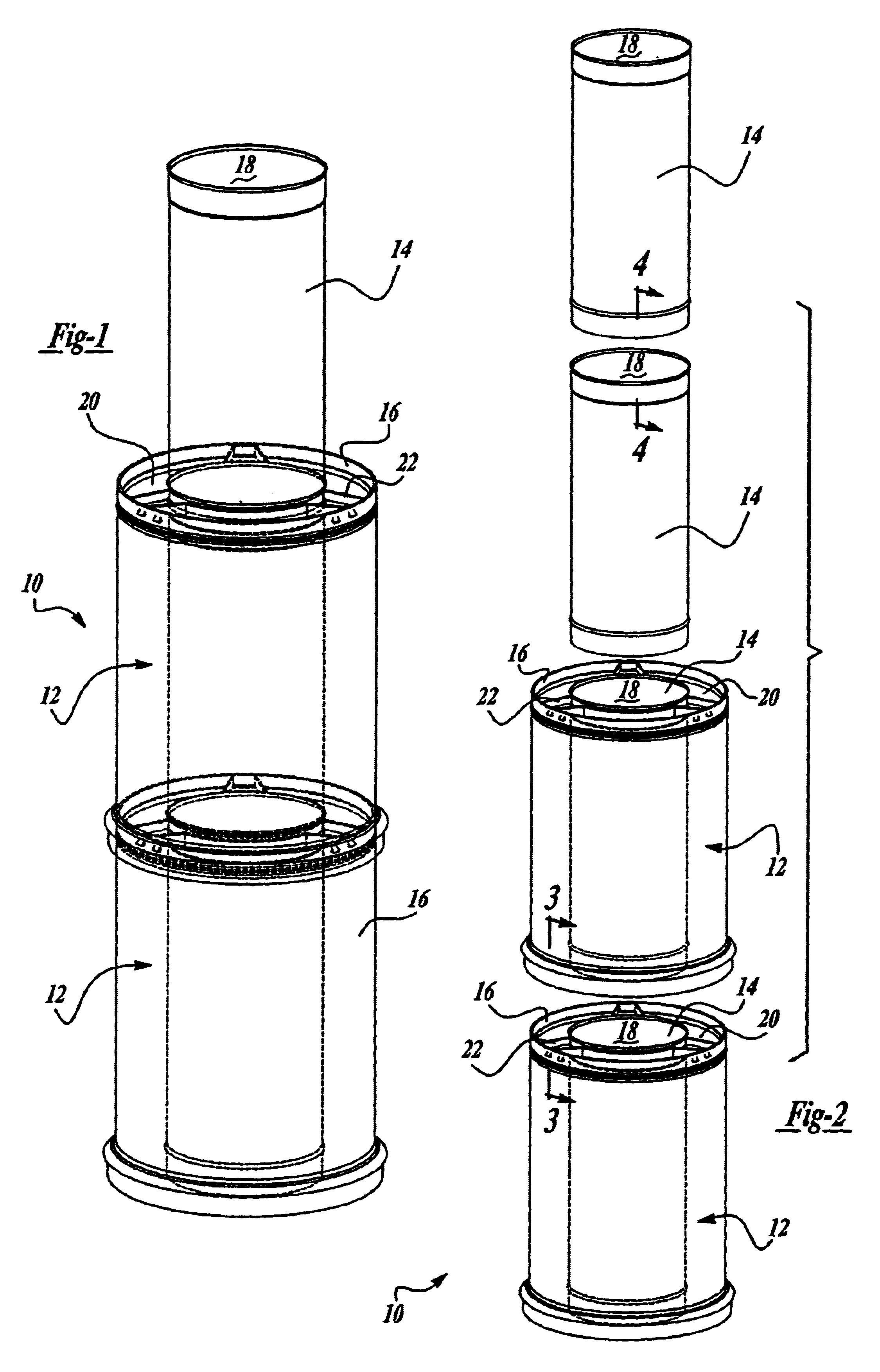
Referring first to FIGS. 1 and 2, there is shown at least a portion of a vent pipe 10 adapted to direct combustion gases from an appliance to a remote location for venting while also supplying oxygenated air to the appliance to aid in the combustion process. The vent pipe 10 maintains separation of the exhaust gases and the inlet gases to prevent mixing. A typical installation may include connection to a fireplace for venting combustion exhaust to the exterior of the building. In addition to facilitating the flow of gases to and from the appliances the vent pipe 10 must withstand extreme temperatures while disposed within the structure surrounding the appliance. Such temperatures not only have insulative considerations but subject the vent pipe 10 to thermal expansion and contraction. The vent pipe 10 will be generally described in connection with venting of exhaust gases from a fireplace although it is to be understood that the vent pipe 10 may be used with a variety of appliances ...


PUM


Abstract

A venting system for a direct vent fireplace or other direct vent appliance to direct combustion gases to an exterior area. The direct venting vent pipe facilitates unrestricted lengths of pipe installations. The vent pipe has a double wall construction forming an interior axial passageway and a coaxial outer passageway. The double walls are spaced apart by an insert to maintain coaxial spacing. Sections of the vent pipe are lockingly connected to prevent separation and ensure sealing connection between the pipe sections. Elastic seal members are utilized between the matingly connected sections and a mechanical lock assembly prevents separation.

Description

I. Field of the InventionThis invention relates to chimney pipes for directing exhaust from a fireplace and other appliances to the exterior and, in particular, to an improved joint sealing and locking assembly to connect segments of the vent pipe.II. Description of the Prior ArtHeating appliances have become increasingly popular as homeowners "cocoon" and make use of their homes for entertaining. Gas, real wood and pellet stoves and fireplaces all require the venting of combustion gases to the exterior. It is desirable to direct such combustion gases to the exterior without backdraft. Furthermore, such vent pipes can become hot requiring sufficient insulation around building materials.Multiple wall vent pipes efficiently direct combustion gases through a main central passageway while coaxial passageways created by larger diameter pipes allow not only for the supply of combustion air to the heating appliance but also act as an insulation barrier. However, connection of the pipe sect...

Claims


Application Information

Patent Timeline
Patent Type & Authority Patents(United States)
IPC IPC(8): F23J13/04F23L17/04F23J13/00F23L17/00
CPCF23J13/04F23L17/04F23J2211/101F23J2213/204F23J2213/201F16L9/18
Inventor MAIELLO, DENNIS
Owner CARDINAL IP HLDG LLC
Why Eureka
Try Eureka