Electrically driven brake booster
a brake booster and electric drive technology, applied in the direction of braking systems, rotary clutches, fluid couplings, etc., can solve the problems of poor transmission efficiency, increased weight, and the inability of the master cylinder to be directly operated by the driver manipulating the brake pedal, so as to improve transmission efficiency, reduce weight, and simple construction
- Summary
- Abstract
- Description
- Claims
- Application Information
AI Technical Summary
Benefits of technology
Problems solved by technology
Method used
Image
Examples
second embodiment
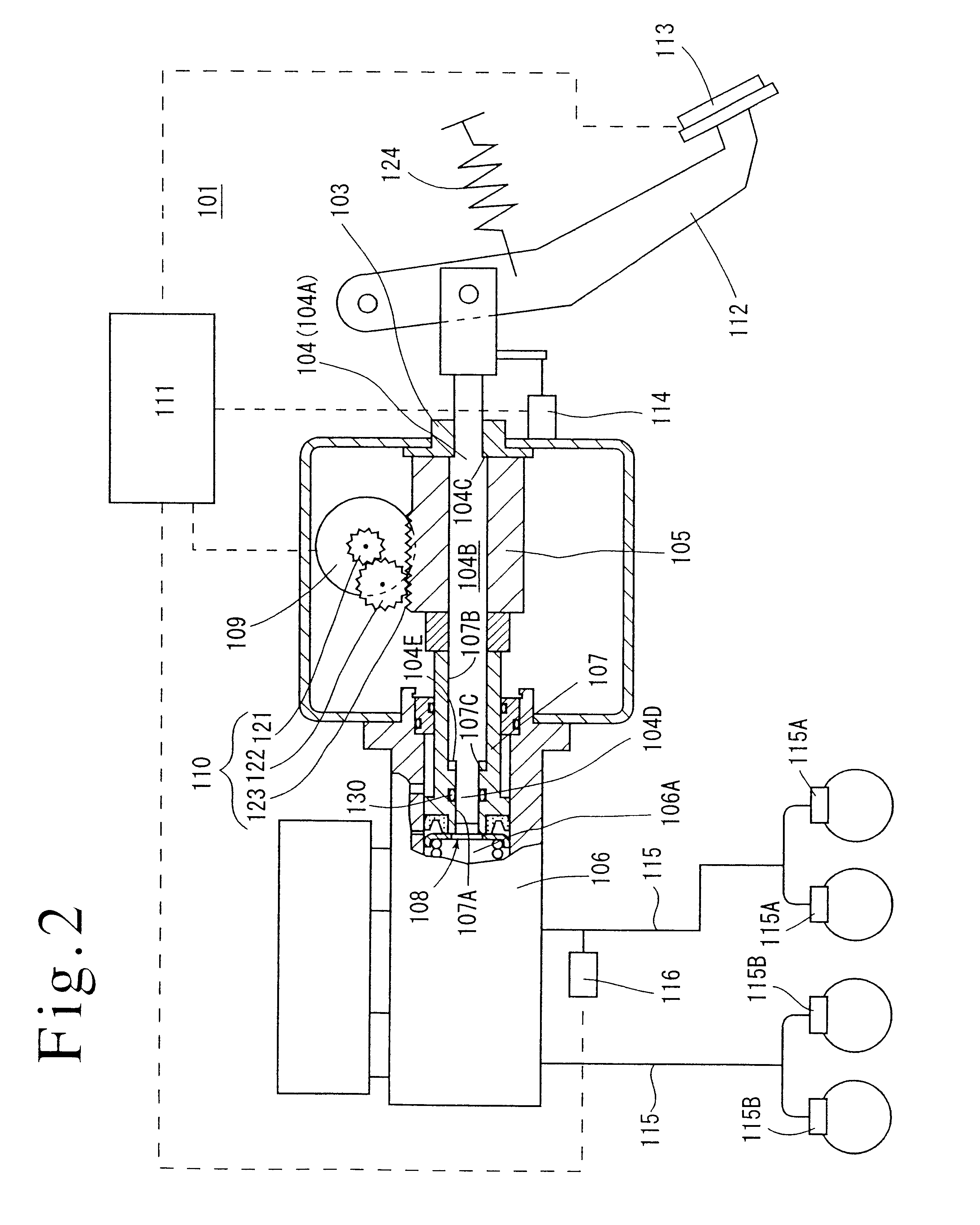
It is to be noted that in the second embodiment, the input member 104 is arranged to be displaceable relative to the output member 105 and the piston 107 of the master cylinder 106, allowing the strokes of the input member 104 and the output member 105 to be different from each other. In this manner, the pedal stroke can be set up independently from the stroke of the piston 107 of the master cylinder 106.
FIG. 3 shows a third embodiment of the invention. What is modified in the third embodiment over the second embodiment is the provision of a spring 233 disposed between a stop member 203 (a housing 202) and an input member 204 to serve as means for urging the input member 204 in the opposite direction from the direction of the input, allowing the stroke of the input member 204 (or a brake pedal 212) to be set up independently from a stroke of a piston 207.
In other respects, the third embodiment is arranged in the similar manner as the second embodiment, and accordingly, corresponding...
third embodiment
The displacement L of the spring 133 is the same as the stroke of the input member 204, and it is seen from the equation (2) that the stroke of the input member 204 is proportional to the input F1 from the brake pedal 212 and has nothing to do to with the stroke of the output member 205 or the piston of the master cylinder 206. Thus, in the third embodiment, the stroke of the brake pedal can be set up independently from the stroke of the piston of the master cylinder 206.
It should be obvious that the third embodiment is capable of achieving a similar functioning and effect as achieved by the second embodiment. In addition, because the stroke of the input member 204 is proportional to the input F1, and is not influenced by the stroke of the output member 205 or the piston 207 of the master cylinder 106, the pedal stroke can be freely set up by changing the spring constant of the spring 233 or the pressure responsive area of the input member 204.
PUM
 Abstract
Description
Claims
Application Information
 - R&D
- Intellectual Property
- Life Sciences
- Materials
- Tech Scout
- Unparalleled Data Quality
- Higher Quality Content
- 60% Fewer Hallucinations
Browse by: Latest US Patents, China's latest patents, Technical Efficacy Thesaurus, Application Domain, Technology Topic, Popular Technical Reports.
© 2025 PatSnap. All rights reserved.Legal|Privacy policy|Modern Slavery Act Transparency Statement|Sitemap|About US| Contact US: help@patsnap.com


