Front light, reflective liquid crystal display device and personal digital assistant

a liquid crystal display device and front light technology, applied in the direction of identification means, lighting and heating apparatus, instruments, etc., can solve the problems of reducing display quality, double image generation, and high cos

Inactive Publication Date: 2003-10-21
MITSUBISHI ELECTRIC CORP
View PDF49 Cites 55 Cited by
  • Summary
  • Abstract
  • Description
  • Claims
  • Application Information

AI Technical Summary

Problems solved by technology

An optical guide plate having the prism angle varied in one same plane is difficult to process and to fabricate with high precision, resulting in higher cost.
Therefore, in most cases, the rib-shaped or fringe-shaped prism structure is visually recognized by the viewer, lowering the display quality.
Further, as the light beam is reflected by the liquid crystal panel and again passes through the optical guide plate, the light beam is refracted to different directions at surfaces of different angles, resulting in the problem that double images are generated.
Otherwise, significant unevenness results in the illumination.
When the light entering the optical guide plate has wide angular distribution, the emitted light also comes to have wide angular distribution, and hence it becomes difficult to attain high brightness.
The conventional front lights having the above described structures have the problems that the fringe-shaped prism structure of the optical guide plate is visually recognized, and display quality is degraded because of emission lines or unevenness.
Further, it has been impossible to control angular distribution of the emitted light from the front light, and hence it has been difficult to ensure high brightness.
It should be noted, however, that the above described efficiency lowers when the two-dimensional size is small, as in the case of a front light of a liquid crystal display device mounted on a personal digital assistant, and hence it becomes difficult to obtain a display image of a desired brightness.
As already described, when the two-dimensional size is small as in the case of a front light of a reflective liquid crystal display device mounted on a personal digital assistant, the above described efficiency becomes low without reflective film, and it becomes difficult to obtain the display image of a desired brightness.
However, the light beam that once goes out from the grooves of the second optical guide plate, reflected by the reflector plate and returned to the groove portions come to have wide width in the direction of progress, and hence directivity is considerably degraded.
When a metal film is directly formed on the resin material, sometimes adhesion therebetween is not sufficient.
When the width of the second optical guide plate is smaller than 2 mm, it is difficult to supply light beams of uniform brightness over the widthwise direction of the main optical guide plate.

Method used


Image

  • Front light, reflective liquid crystal display device and personal digital assistant
  • Front light, reflective liquid crystal display device and personal digital assistant
  • Front light, reflective liquid crystal display device and personal digital assistant

Examples


reference example 1

--Angle of the Gentle Slope Surface, Metal Mold for the Projected Portions Arranged Between Flat Portions

(1) Overall Structure

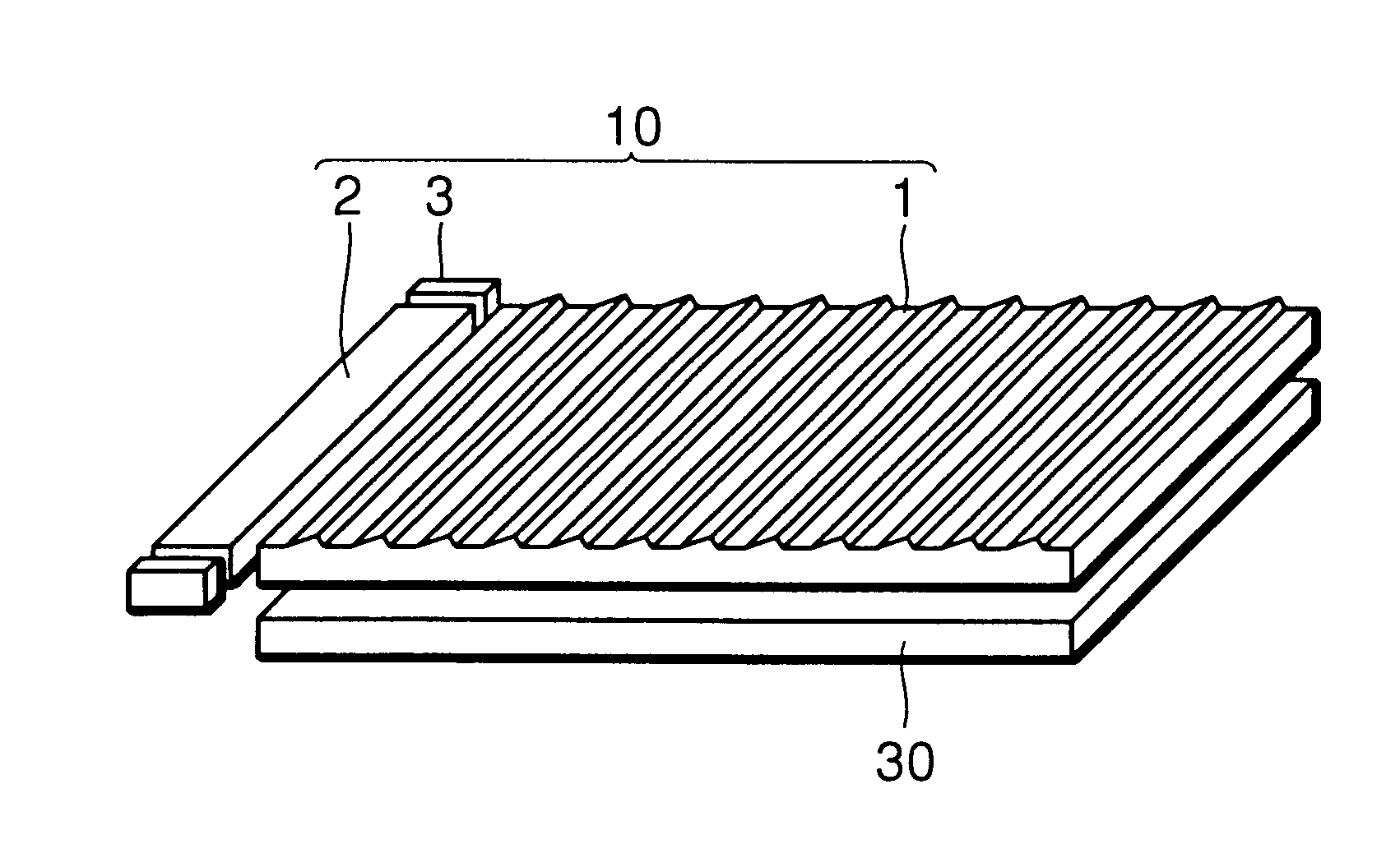
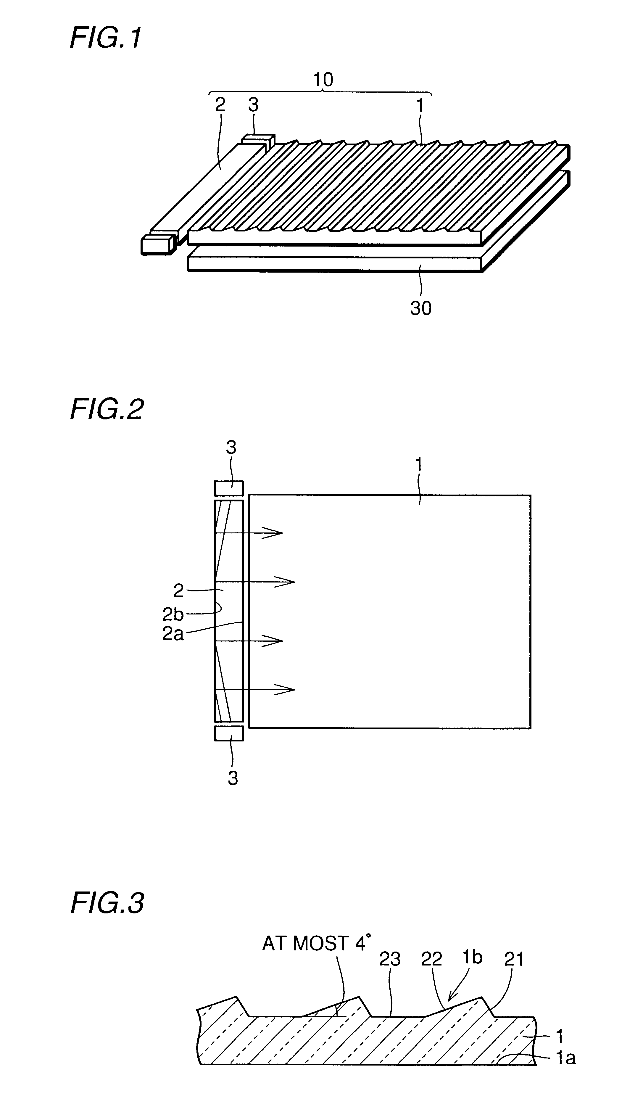
FIGS. 1 to 8 are illustrations of the front light in accordance with Reference Example 1. The bar shaped light source for the main optical guide plate 1 consists of a second optical guide plate 2 extending in the widthwise direction along an end portion of the main optical guide plate 1, and LEDs 3 as point light sources, arranged at end portions of the second optical guide plate, as shown in FIG. 1. As shown in FIG. 2, light beams emitted from LEDs 3 enter end portions of the second optical guide plate, propagated through the second optical guide plate, and by the light extracting structure formed on the fourth surface 2b of the second optical guide plate, the light beams are emitted from the third surface 2a to the main optical guide plate 1. On the second surface 1b of the main optical guide plate 1, a plurality of projections, each having a prism-shaped c...

reference example 2--

Effects Attained by Incrementing Height of the Prism-Shaped Projections of the Main Optical Guide Plate

In the present reference example, a front light will be described in which the height of the prism-shaped projections of the main optical guide plate is incremented along the depth direction. The structure of the front light in the present reference example other than the main optical guide plate is the same as the front light of Reference Example 1. Referring to FIG. 10, the height of the prism-shaped projections 21, 22 becomes higher at positions deeper from the side where the light beams enter, so that the area of reflective surface per unit length in the depth direction increases. As there is flat portion 23 between the projections, the sides 21 and 22 constituting the prism-shape form the same angle at any prism-shaped projections. Therefore, the metal mold for main optical guide plate 1 shown in FIG. 10 can be readily manufactured, and hence, the main optical guide plate can ...

embodiment 1

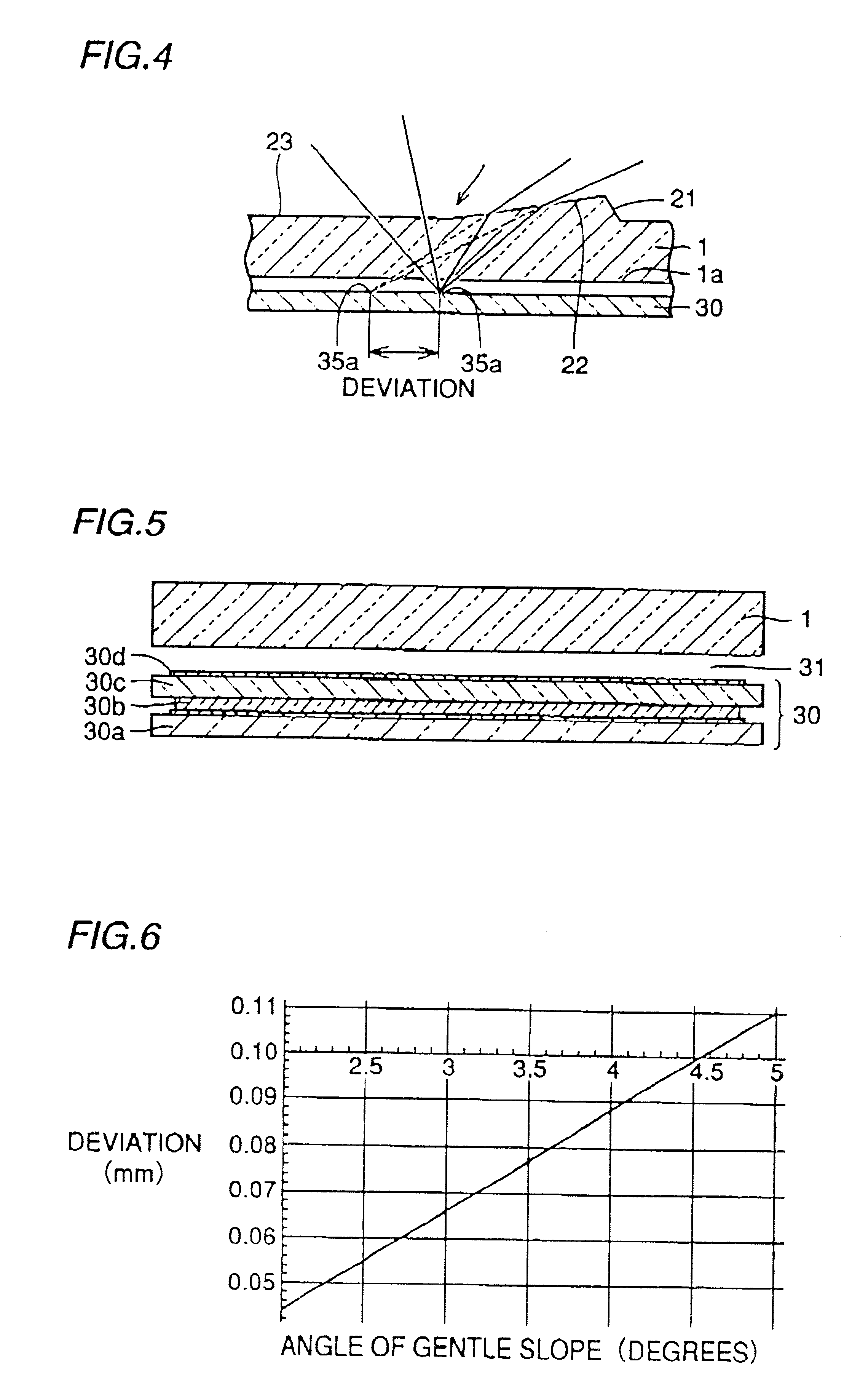
(P3) At this time, between the light beam that is refracted and passed through the gentle slope surface and the light beam that passed through the flat portion, deviation between image points result, causing blurred display, degrading display quality significantly. As disclosed in Embodiment 1, the deviation can be made unrecognizable, by setting the angle of the gentle slope surface to be 40 or smaller.


PUM

PropertyMeasurementUnit
angleaaaaaaaaaa
widthaaaaaaaaaa
lengthaaaaaaaaaa

Abstract

A compact and light weight front light, a reflective liquid crystal display device, and a personal digital assistant providing an image display of uniform brightness with high efficiency are provided. The front light includes a main optical guide plate and a second optical guide plate. The second optical guide plate is arranged at an end of the main optical guide plate along the widthwise direction, and, on an end surface opposite an end surface facing the main optical guide plate, grooves forming prisms are aligned along the longitudinal direction, extending in the depth direction. The front light further includes a point light source arranged at an end, in the longitudinal direction, of the second optical guide plate, and a reflective film covering the surfaces of the grooves.

Description

1. Field of the InventionThe present invention relates to a front light arranged in front of a display device to improve brightness and uniformity of brightness of the image plane on the display device, as well as to a reflective liquid crystal display device and a personal digital assistant.2. Description of the Background ArtFIG. 57A is a schematic cross section representing an example of a conventional front light (Japanese Patent Laying-Open No. 8-94844). FIG. 57A shows a cross section of the front light as a whole, and FIG. 57B is a partially enlarged illustration of an upper surface of an optical guide plate. The optical guide plate 101 of the front light has a surface 101a (hereinafter referred to as the "first surface") opposing to the display device 130 and an upper surface 101b (hereinafter referred to as a "second surface") opposite to the first surface, and on the second surface, a plurality of grooves each having a prism-shaped cross section are provided extending as ri...

Claims


Application Information

Patent Timeline
Patent Type & Authority Patents(United States)
IPC IPC(8): F21V8/00G02B6/00F21Y101/02G02F1/1335G02F1/13357G09F9/00
CPCG02B6/0018G02B6/002G02B6/0061G02B6/0036G02B6/0038G02B6/0028G02F1/1335
Inventor SASAGAWA, TOMOHIROODA, KYOICHIROYUUKI, AKIMASASUGAWARA, NAOTOYOKOI, MASAHIROMORODA, MASAHISA
Owner MITSUBISHI ELECTRIC CORP
Why Eureka
Try Eureka