Passive safety system

a safety system and passive technology, applied in the direction of pedestrian/occupant safety arrangement, instruments, tractors, etc., can solve the problem of difficult to calculate a precise integrated valu

Inactive Publication Date: 2003-10-21
MITSUBISHI ELECTRIC CORP
View PDF15 Cites 16 Cited by
  • Summary
  • Abstract
  • Description
  • Claims
  • Application Information

AI Technical Summary

Benefits of technology

to provide a passive safety system calculating precisely a deceleration caused by an impact at the time of collision and calculating precisely a deceleration without accumulating the acceleration integral without adding a major processing to the existing constitution in normal driving.
The passive safety control means of the passive safety system may have features of computing a physical quantity based on the impact acceleration detection signal inputted from the acceleration sensor, setting maximum and minimum reference values of the physical quantity in normal driving, performing a computation with respect to addition of a present acceleration inputted from the acceleration sensor to an integrated acceleration value at this point in time when the physical quantity crosses a range defined between the maximum and minimum reference values, measuring a period of time after the physical quantity exceeds the range, and postponing a reset process of the integrated acceleration value when the measured time period is shorter than a required period. In this way, it is possible to postpone a reset process of the integrated acceleration value when the physical quantity provisionally enters within a reference value range due to a vibration component of collision, and calculate further precisely the deceleration at the time of collision.

Problems solved by technology

In this case, since it is however difficult to reset in good timing, a reset process means for resetting the integrated value in good timing must be newly added to the existing constitution.
Since a ratio subtracted when a low-impact is inputted over a long time is however different from a ratio when a high-impact is inputted over a short time, it is difficult to calculate a precise integrated value.

Method used


Image

  • Passive safety system
  • Passive safety system
  • Passive safety system

Examples


embodiment 1

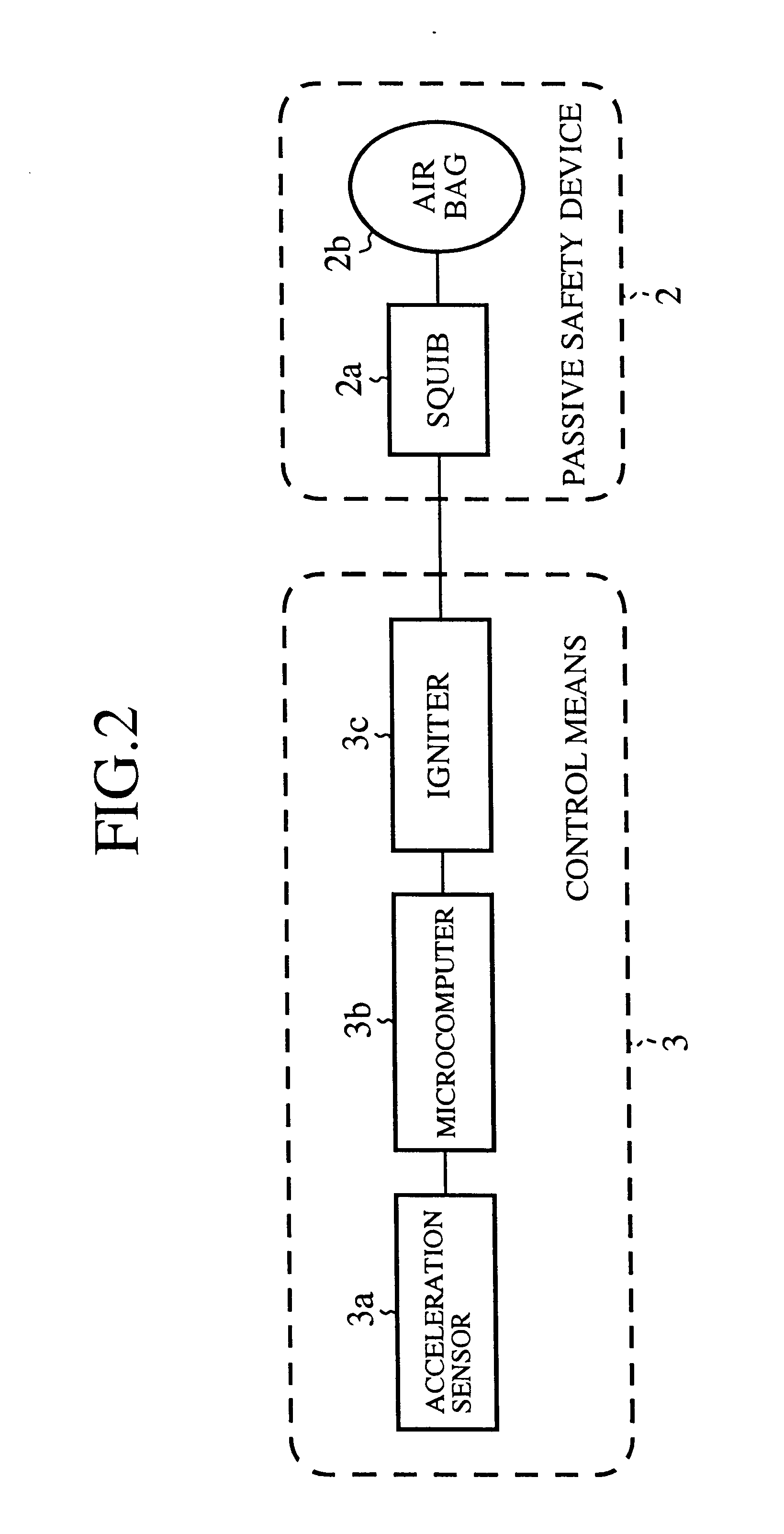
FIG. 2 is a general block diagram showing a passive safety system as embodiment 1 according to the present invention. Components of the embodiment 1 common to the conventional components shown in FIG. 1 are denoted by the same reference numerals and further description will be omitted.

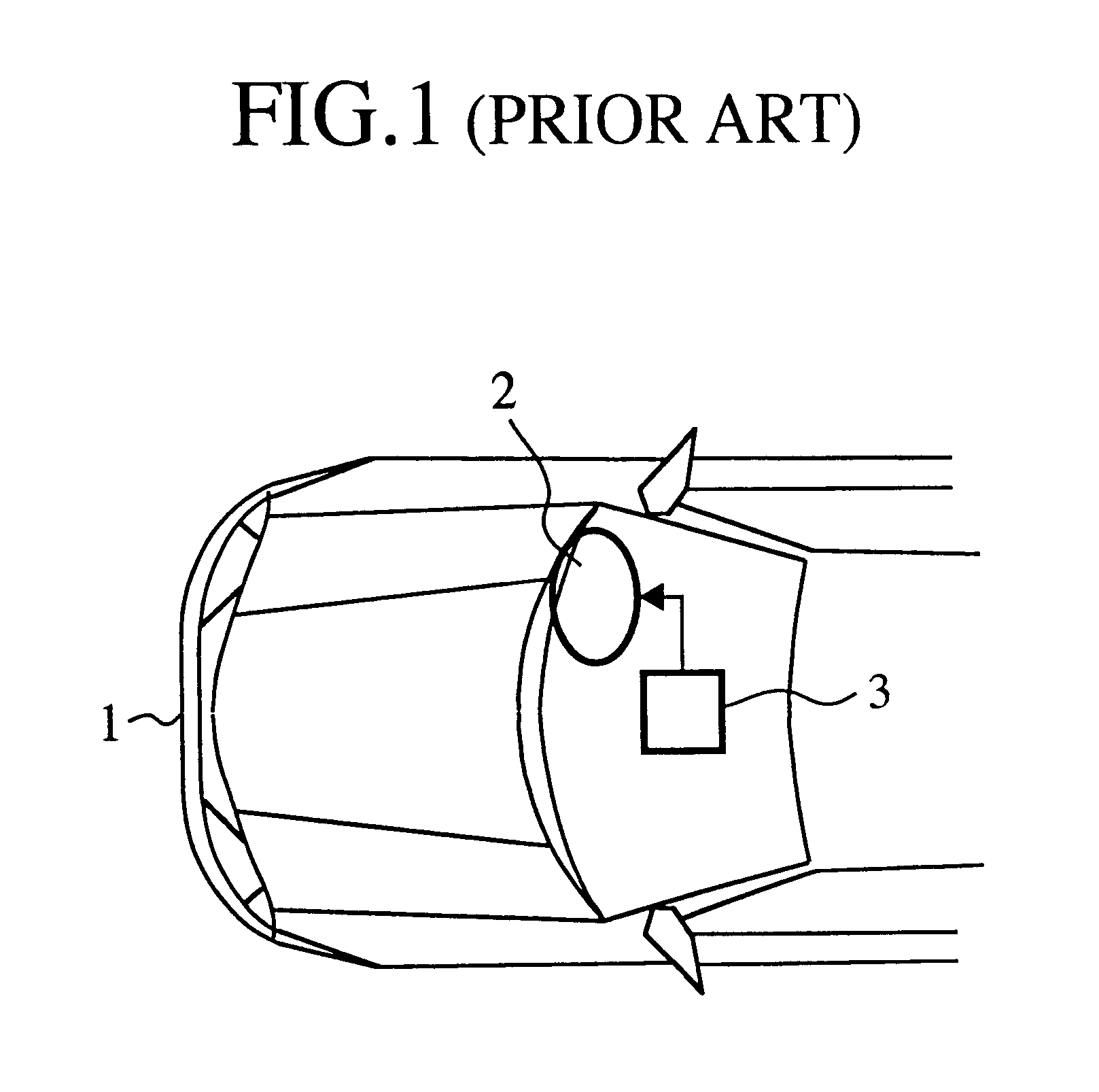
In FIG. 2, a reference numeral 2 denotes a passive safety device mounted on the vehicle 1 (see FIG. 1). The passive safety device 2 includes a squib (initiation device) 2a and an airbag 2b expanded by the squib 2a. A reference numeral 3 denotes a control means controlling the passive safety device 2. The control means 2 includes an acceleration sensor 3a for detecting impact acceleration caused at the time of front-collision of the vehicle 1, a microcomputer 3b inputted the acceleration detection signal from the acceleration sensor 3a as a digital data due to an A / D converter, and an igniter 3c receiving an output signal from the microcomputer 3b to supply an ignition current to the squib 2a.
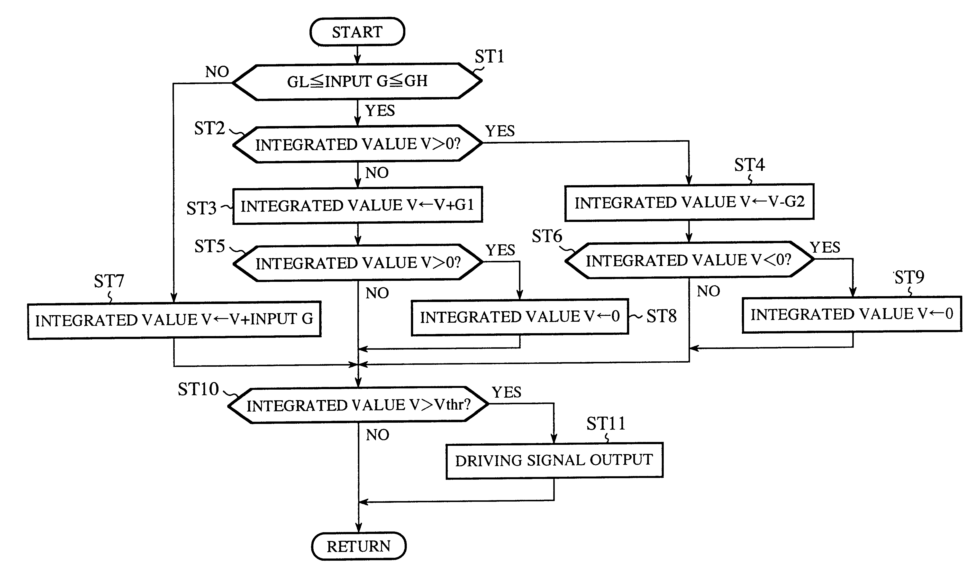
An operati...

embodiment 2

FIG. 7 is a plane view showing a front section of a vehicle providing with a passive safety system as embodiment 2 according to the present invention, and FIG. 8 is a block diagram showing the passive safety system of FIG. 7. Components of the embodiment 2 common to the components shown in FIG. 1 and FIG. 2 are denoted by the same reference numerals and further description will be omitted.

In FIG. 7, a reference numeral 1 denotes a vehicle, and a reference numeral 2 denotes a passive safety device for front-collision mounted on the vehicle 1. A reference numeral 4 denotes a passive safety device for rear-collision mounted on the vehicle 1. A reference numeral 3 denotes a common control means for driving both of the passive safety devices 3 and 4. As shown in FIG. 8, the control means 3 includes an acceleration sensor 3a for detecting impact acceleration caused at the time of front-collision of the vehicle 1, a microcomputer 3b inputted the acceleration detection signal from the accel...

embodiment 3

FIG. 11 is a plane view showing a front section of a vehicle providing with a passive safety system as embodiment 3 according to the present invention, and FIG. 12 is a block diagram showing the passive safety system of FIG. 11. Components of the embodiment 3 common to the components shown in FIG. 2 to FIG. 10 and FIG. 1 are denoted by the same reference numerals and further description will be omitted.

In FIG. 11, a reference numeral 5 denotes a right-collision passive safety device mounted on the vehicle 1, and similarly a reference numeral 6 denotes a left-collision passive safety device mounted on the vehicle 1.

In FIG. 12, a reference numeral 3f denotes a right-collision igniter, and a reference numeral 3g denotes a left-collision igniter. These igniters 3f and 3g receive output signals from the microcomputer 3b to drive the right-collision passive safety device 5 and the left-collision passive safety device 6, respectively. Here, side-collision airbags are listed up as an exampl...


PUM


Abstract

A passive safety system has a passive safety device mounted on a vehicle, and a passive safety control means having an acceleration sensor detecting acceleration caused by an impact at the time of collision. The passive safety control means receives input an impact acceleration detection signal from the acceleration sensor and operates controllably the passive safety device. Further, the passive safety control means computes a physical quantity based on the impact acceleration detection signal inputted from the acceleration sensor, sets maximum and minimum reference values of the physical quantity in normal driving, performs a computation with respect to addition of a present acceleration inputted from the acceleration sensor to an integrated acceleration value at this point in time when the physical quantity crosses a range defined between the maximum and minimum reference values, and performs a computation with respect to a reset process of the integrated acceleration value when the physical quantity remains within the range defined between the maximum and minimum reference values.

Description

1. Field of the InventionThe present invention relates to a passive safety system including a passive safety device and a control device operating controllably the passive safety device. Especially, the present invention relates to a passive safety system having features of determining whether impacts at the time of collision necessitate an operation of the passive safety device or not, and controlling the operation of the passive safety device based on the determined result.2. Description of the Prior ArtFIG. 1 is a plan view showing a front section of a vehicle (automobile) including a conventional passive safety system. In the drawing, a reference numeral 1 denotes a vehicle, 2 denotes an airbag acting as a passive safety device arranged at a front of seats mounted on the vehicle 1, and 3 denotes a passive safety control means developing the airbag 2. The passive safety control means 3 includes an acceleration sensor (not shown) and a microcomputer (not shown) receiving input an ...

Claims


Application Information

Patent Timeline
Patent Type & Authority Patents(United States)
IPC IPC(8): B60R21/01B60R21/16B60R21/013B60R21/015
CPCB60R21/0132B60R21/0156B60R2021/01304B60R2021/01302B60R21/0133B60R21/01336B60R21/01B60R2021/01322
Inventor YAMASHITA, TOSHIYUKI
Owner MITSUBISHI ELECTRIC CORP
Why Eureka
Try Eureka