Turbomachine with radial-flow compressor impeller

a compressor impeller and radial flow technology, which is applied in the direction of machines/engines, stators, liquid fuel engines, etc., can solve the problems of compressor impeller fracture, compressor impeller vanes are completely destroyed, compressor impellers can be so greatly weakened,

Inactive Publication Date: 2003-10-28
MAN B & W DIESEL AG
View PDF9 Cites 21 Cited by
  • Summary
  • Abstract
  • Description
  • Claims
  • Application Information

AI Technical Summary

Benefits of technology

The rigid fixing arrangement of the spiral casing on the bearing casing, and the casing insert piece itself, can absorb considerably more kinetic energy than the flexible fixing arrangement of the casing insert piece on the spiral casing. This ensures that the casing insert piece can, in an emergency, move away from the compressor impeller in the axial direction. In this way, the kinetic energy of the compressor impeller pieces can be largely absorbed by conversion into deformation energy and the heat resulting from it. The residual kinetic energy of the fragments can be absorbed by the casings.
The spiral casing is configured with an inner cylinder, which at least partially surrounds the casing insert piece, on which inner cylinder, the casing insert piece is attached, to form a hollow space, by means of a fixing arrangement which is flexible in the axial direction. This ensures a high level of protection of the spiral casing itself from impact and an effective "brake" to combat any emergence of fragments from the turbocharger. In a particularly advantageous manner, the rigid fixing arrangement of the compressor casing is configured by means of a firm flange connection of the spiral casing to the bearing casing and the flexible fixing arrangement of the casing insert piece is configured by means of a reduced-shaft screw fixing arrangement in the axial direction through the inner cylinder of the spiral casing.
In a particularly advantageous manner, the bearing casing wall provided for the rigid fixing arrangement of the spiral casing is arranged so that it is drawn downwards in the radial direction to above the outer tip of the outer contour of the compressor impeller, while forming a gap, so that an additional "brake", i.e. security against radial emergence of fragments of the compressor impeller, is provided.
The compressor casing is preferably positioned by means of the outer spiral casing, while forming a joint on the bearing casing, in such a way that the outer spiral casing comprising the deflected duct section, is drawn inward in the radial direction B past the rigid fixing arrangement of the compressor casing on the bearing casing. The rigid fixing arrangement is arranged so that it is located further outward, in the radial direction B, than the joint between the spiral casing and bearing casing. This measure, comprising the particular arrangement of the joint, ensures that the rigid fixing arrangement of the compressor casing on the bearing casing hardly suffers any loads from fragments possibly becoming wedged in the flow duct, by which means, breakage of the compressor casing is excluded to an even greater extent.

Problems solved by technology

After lengthy operation under unfavorable conditions, such a compressor impeller can be so greatly weakened by corrosion, erosion and aging that fracture of the compressor impeller cannot be excluded.
In the process, the compressor impeller vanes are completely destroyed and the remaining hub body jams between the bearing casing and the compressor casing.
In the case of large turbochargers, the casing wall thicknesses are usually reduced for technical casting reasons so that, in the case of such loads, the fracture limit of the material is rapidly reached and casing fractures can occur.
Fragments can then emerge from the turbocharger, with substantial consequential damage.
The fixing arrangement is axially flexible and is less secure against fracture than the rigid fixing of the outer spiral casing to the bearing casing.

Method used


Image

  • Turbomachine with radial-flow compressor impeller
  • Turbomachine with radial-flow compressor impeller

Examples


Embodiment Construction

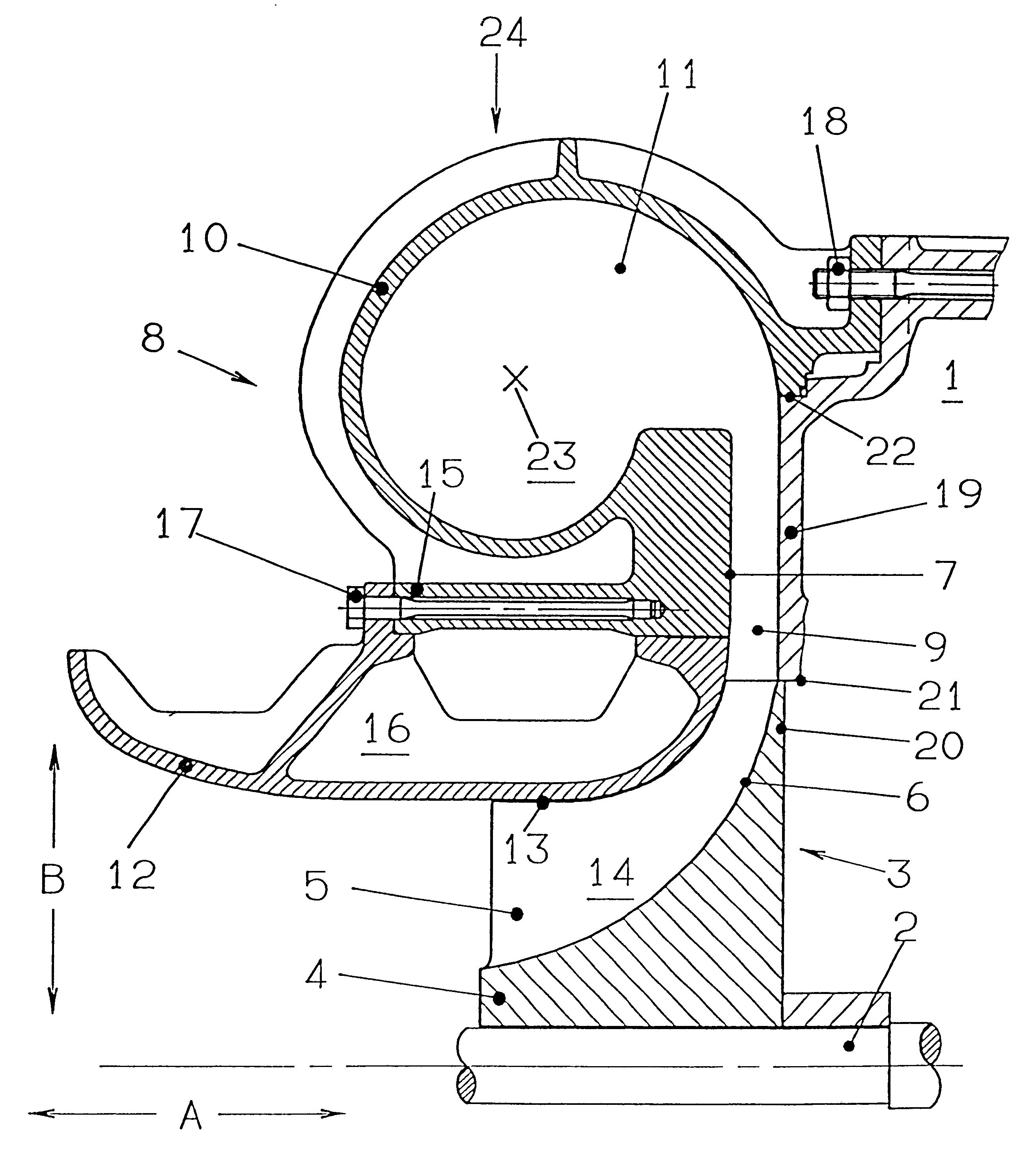
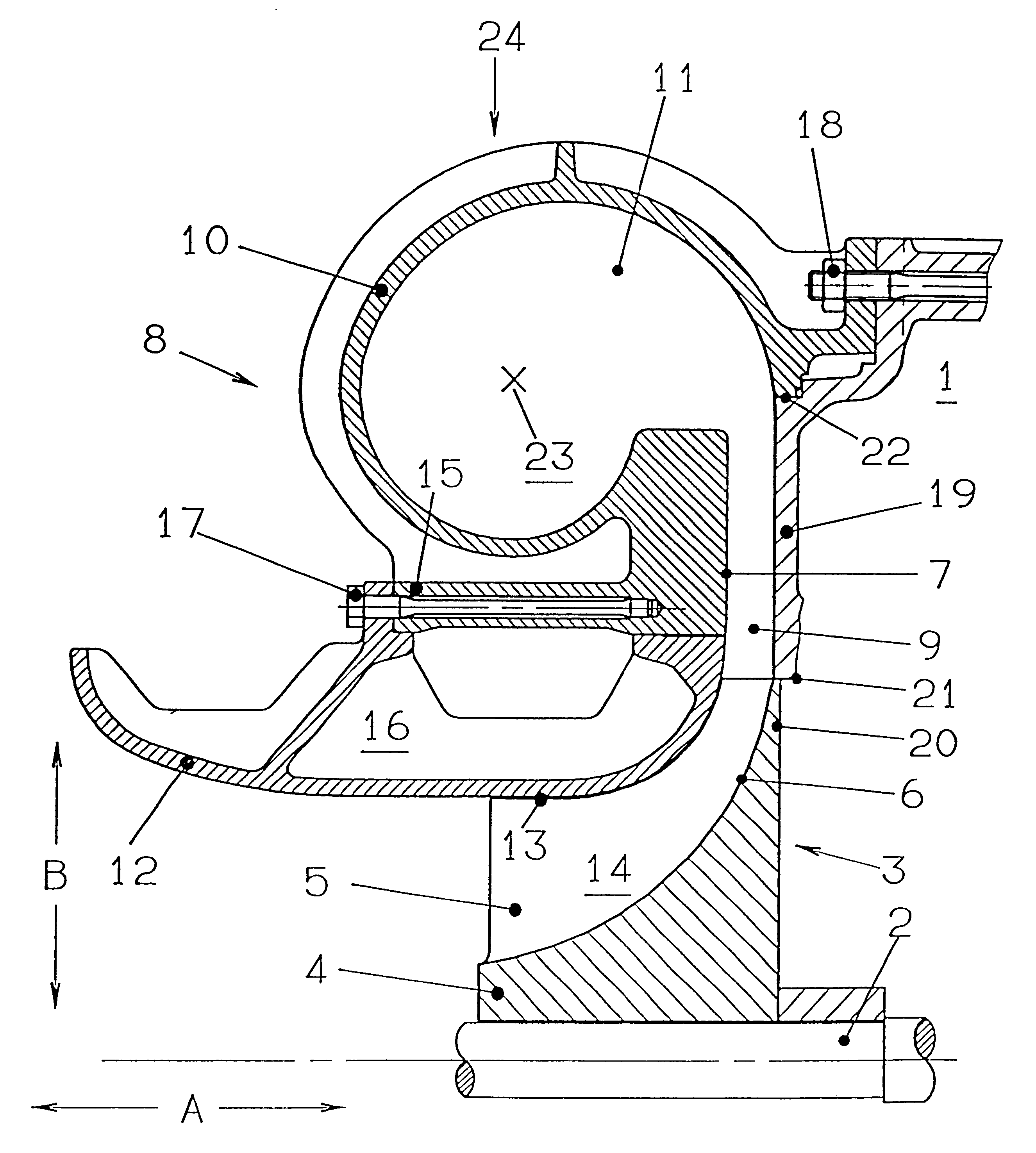
The exhaust gas turbocharger of the type based on the drawing has a shaft 2 supported in its central length region in a bearing casing 1, which carries on its ends protruding beyond the bearing arrangement a turbine wheel (not represented here) and a radial-flow compressor impeller 3 which is diagrammatically represented in the drawing.

The compressor impeller 3 represented has a hub 4 accommodated on and rotating with the shaft 2 driven by the turbine wheel, which hub 4 is equipped at its periphery with radially protruding vanes 5. The outer contour 6 of the hub 4, together with the inner contour 7 of a compressor casing 8, bounds a flow duct 9, which is deflected from the axial direction A into the radial direction B, becomes narrower towards the outside and whose cross section corresponds to the configuration of the vanes 5. The compressor casing 8 is fastened to the bearing casing 1 by means of a rigid fixing arrangement 18. The diameter of the hub 4 and the vanes 5 increases fro...


PUM


Abstract

A compressor casing with a volute-shaped flow duct is fastened by means of a rigid fixing arrangement to the bearing casing of the turbomachine, with simple and low-cost means in such a way that the emergence of fragments of a burst compressor impeller from the compressor casing can be prevented. The compressor casing has an outer spiral casing, which surrounds a duct section of the flow duct deflected towards the outside into the radial direction (B), and an inner casing insert piece, which is provided in the radial direction (B) between the spiral casing and the compressor impeller and whose inner contour, together with the outer contour of the hub of the compressor impeller, forms the duct section of the flow duct extending essentially in the axial direction (A). The spiral casing is configured with an inner cylinder at least partially surrounding the casing insert piece, on which inner cylinder the casing insert piece is attached by means of a fixing arrangement, which is flexible in the axial direction (A), to form a hollow space. The flexible fixing arrangement of the casing insert is less secure against fracture than the rigid fixing arrangement of the compressor casing on the bearing casing.

Description

1. Field of the InventionThe invention relates to a turbomachine with radial-flow compressor impeller, which is enclosed by a spiral-shaped compressor casing with a volute-shaped flow duct having an essentially axially deflecting section and an essentially radially deflecting section. The casing includes an outer spiral casing, which includes the radially deflecting section and is rigidly fixed to the bearing casing, and an inner casing insert piece having an inner contour which with the outer contour of the hub forms the axially deflecting section.2. Description of the Related ArtThe fundamental construction and the mode of operation of such turbomachines, such for example as a centrifugal compressor of a turbocharger, are known per se and therefore require no more detailed explanation in the present connection. Thus, for example, DE 195 02 808 C2 describes a generic turbomachine in the form of a centrifugal compressor of a turbocharger, within whose spiral-shaped compressor casing...

Claims


Application Information

Patent Timeline
Patent Type & Authority Patents(United States)
IPC IPC(8): F04D29/60F04D29/62F04D29/42F04D1/00F04D29/44
CPCF04D29/4206F04D29/624F05B2250/25F05B2250/15F05D2220/40F01D9/026F01D25/24F04D1/00
Inventor BARTHOLOMA, KLAUSSCHMIDT, WOLFGANG
Owner MAN B & W DIESEL AG
Why Eureka
Try Eureka