Hybrid arched overfilled structure

a technology of arched structure and overfilled structure, which is applied in the direction of building roofs, foundation engineering, artificial islands, etc., can solve the problems of uneconomical construction methods, reduce the finished quality of formed concrete, and expensive and time-consuming provision of such outside form work, so as to reduce the initial capital investment required, less unwieldy, and work easier

Inactive Publication Date: 2003-11-04
CONTECH ENGINEERED SOLUTIONS
View PDF8 Cites 45 Cited by
  • Summary
  • Abstract
  • Description
  • Claims
  • Application Information

AI Technical Summary

Benefits of technology

It is another object of the present invention to provide an overfilled arched bridge and method of construction therefor which reduces initial capital investment required.
It is another object of the present invention to provide an overfilled arched bridge and method of construction therefor which is expeditious to produce.
These, and other, objects are achieved by a hybrid arched overfilled bridge structure and method for constructing the same which combines pre-cast elements with cast-in-place sections. The hybrid bridge thus realizes the advantages associated with precast elements and with cast-in-place elements while omitting most, if not all, of the disadvantages associated therewith. The pre-cast elements can be small and thus will avoid the aforediscussed transportation-related costs and problems, and the cast-in-place sections will avoid the above-discussed formwork problems. The hybrid bridge embodying the present invention thus takes advantage of both methods of construction while avoiding most, if not all, the problems associated with each of the methods of construction.
Furthermore, since the pre-cast side elements make up a shorter sector of the arch than is the case with prior bridges, it is possible to pre-cast them lying flat (that is, comparable to a curved slab) rath

Problems solved by technology

This method generally requires formwork on both the inside and the outside of the arch profile as the sides of the arch are generally too steep to be cast without the support provided by formwork.
The provision of such outside form work is both costly and time consuming and may reduce the finished quality of the formed concrete.
This renders this method of construction uneconomical if the molds cannot be re-used to supply elements for the construction of many arch bridges.
Problems associated with the transport of such arches and the requirement of a construct

Method used


Image

  • Hybrid arched overfilled structure
  • Hybrid arched overfilled structure
  • Hybrid arched overfilled structure

Examples


Embodiment Construction

Other objects, features and advantages of the invention will become apparent from a consideration of the following detailed description and the accompanying drawings.

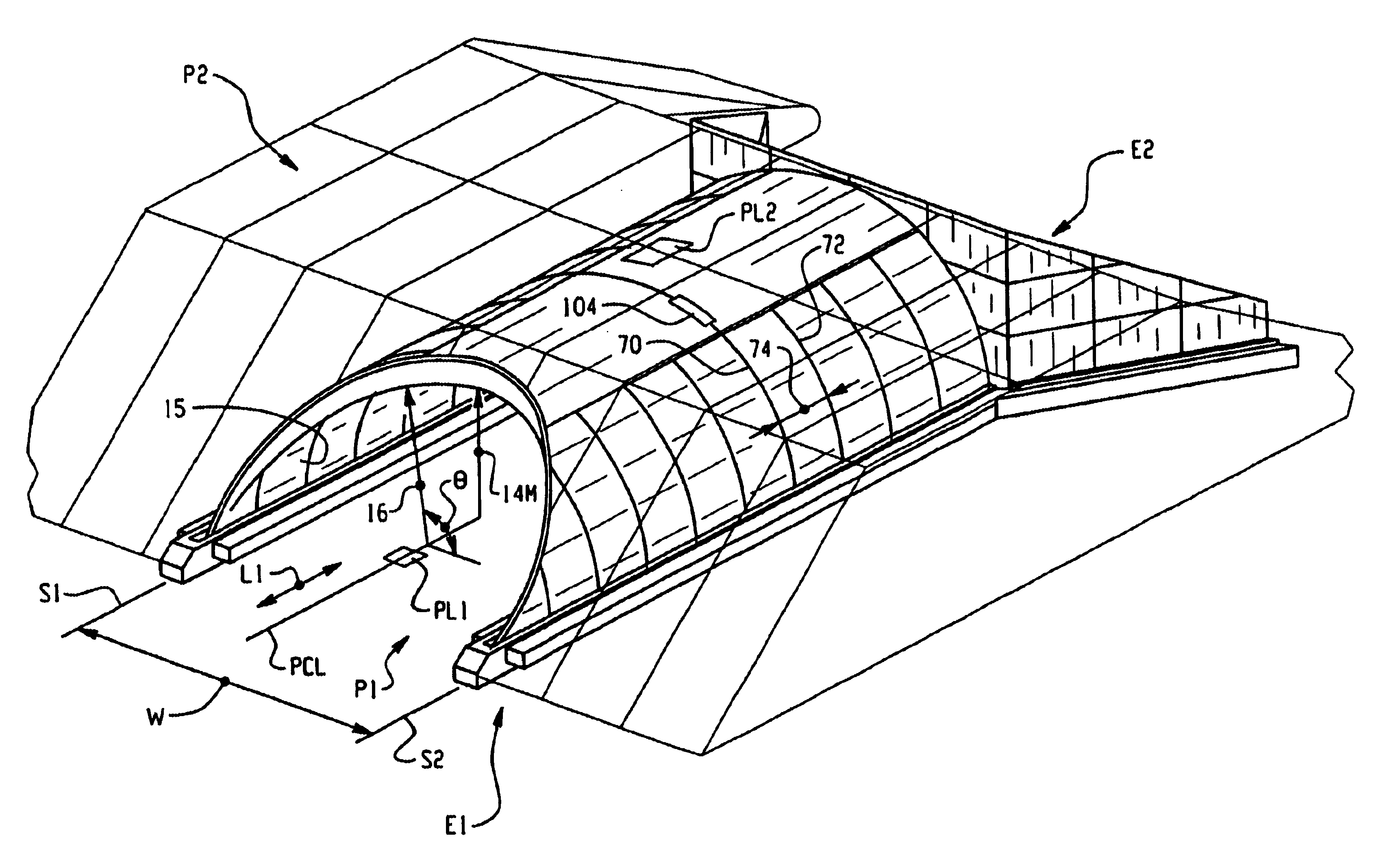
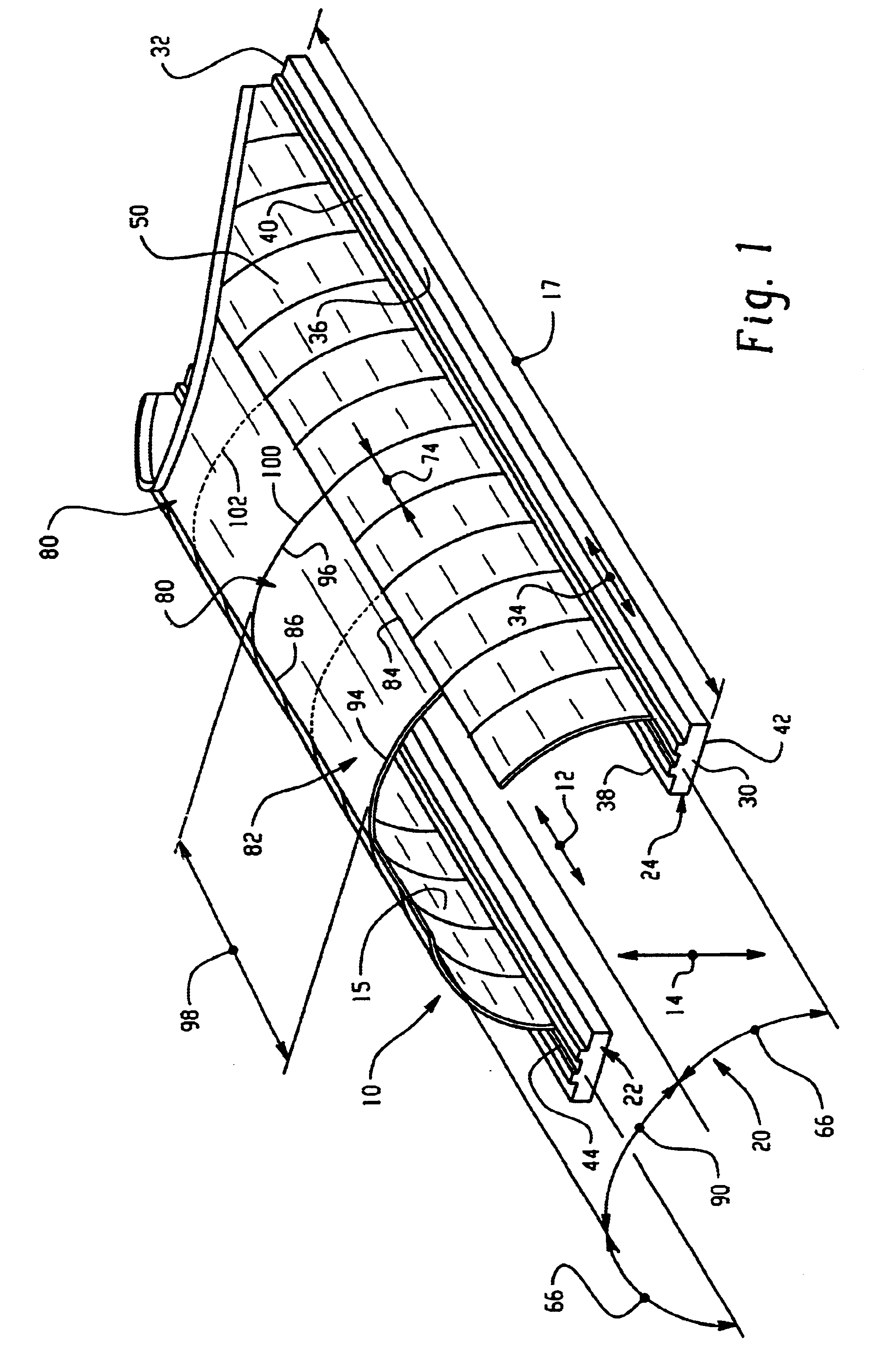
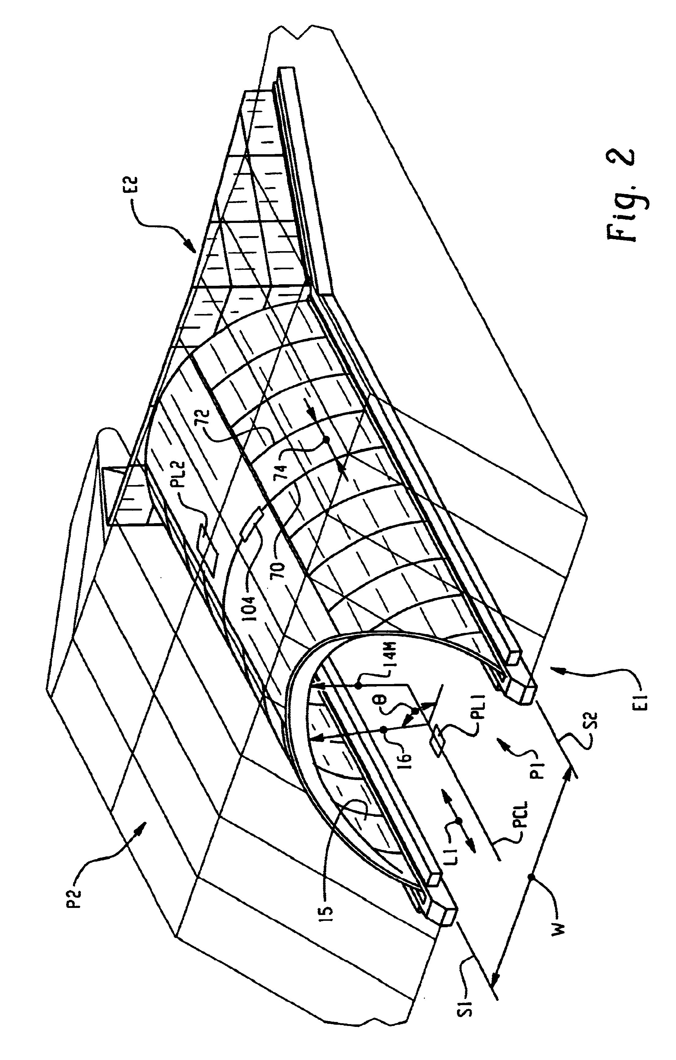
The hybrid arched overfilled bridge structure and method of construction embodying the present invention includes a concrete arch span with three major components: side elements, with one sector on each side of the arch formed of pre-cast side elements; and one sector located between the side elements formed of cast-in-place concrete. The concrete can be reinforced if desired.

Shown in FIGS. 1-5 is a hybrid arched overfilled bridge structure 10 of the present invention. As can be seen in FIGS. 2 and 3, the bridge structure is associated with a first pathway P1 that is located at one level in a vertical plane and supports a second pathway P2 above that first pathway. Examples of the pathways include roadways, footpaths, waterways, railroad right-of-ways, finished and unfinished paths, and the like as is well known in the ...


PUM

PropertyMeasurementUnit
Angleaaaaaaaaaa
Angleaaaaaaaaaa
Lengthaaaaaaaaaa

Abstract

A hybrid arched overfilled structure includes a combination of pre-cast side elements and at least one cast-in-place crown sector element. The side elements are pre-cast generally in a horizontal orientation and subsequently lifted into place. The crown sector element is cast in place between the side elements. In one form of the invention, each of the three sections makes up about one-third of the overall arch span.

Description

The present invention relates to the general art of geotechnical engineering, and to the particular field of overfilled arch structures.Frequently, overfilled bridges formed of precast or cast-in-place concrete are used to support one pathway over a second pathway, which can be a waterway, a traffic route or the like. The terms "overfilled arch" or "overfilled bridge" will be understood from the teaching of the present disclosure, but in general, an overfilled bridge or an overfilled arch is a bridge formed of arch elements that rest on the ground or on a foundation and has soil or the like resting thereon and thereabout to support and stabilize the bridge. The arch form is generally cylindrical in circumferential shape, and in particular a prolate shape; however, other shapes can be used. An example of an overfilled bridge is disclosed in U.S. Pat. Nos. 3,482,406 and 4,458,457, the disclosures of which are incorporated herein by reference.Presently, reinforced concrete overfilled a...

Claims


Application Information

Patent Timeline
IPC IPC(8): E02D29/045
CPCE02D29/045Y10T29/53974
Inventor HEIERLI, WERNER
Owner CONTECH ENGINEERED SOLUTIONS
Why Eureka
Try Eureka