Optical amplifier control

a technology of optical amplifiers and control devices, applied in the field of optical amplifier control, can solve problems such as complex, slow and expensive, and constant output power, and achieve the effects of influencing the transmission performance in a negative way, complicated, slow and expensive, and complicated

Inactive Publication Date: 2003-11-04
TELEFON AB LM ERICSSON (PUBL)
View PDF15 Cites 11 Cited by
  • Summary
  • Abstract
  • Description
  • Claims
  • Application Information

AI Technical Summary

Problems solved by technology

That the output power is constant gives problems if the number of channels are changed--by purpose or by a fault.
The problems with modulating identifying pilot tones on each multiplexed wavelength in order to be able to count the wavelengths is that it is complicated, slow and expensive.
Another problem is that it also influences the transmission performances in a negative way.
An alternative would be to use a separate electrical network, which however is slower.

Method used


Image

  • Optical amplifier control
  • Optical amplifier control
  • Optical amplifier control

Examples


Embodiment Construction

Optical Amplifiers

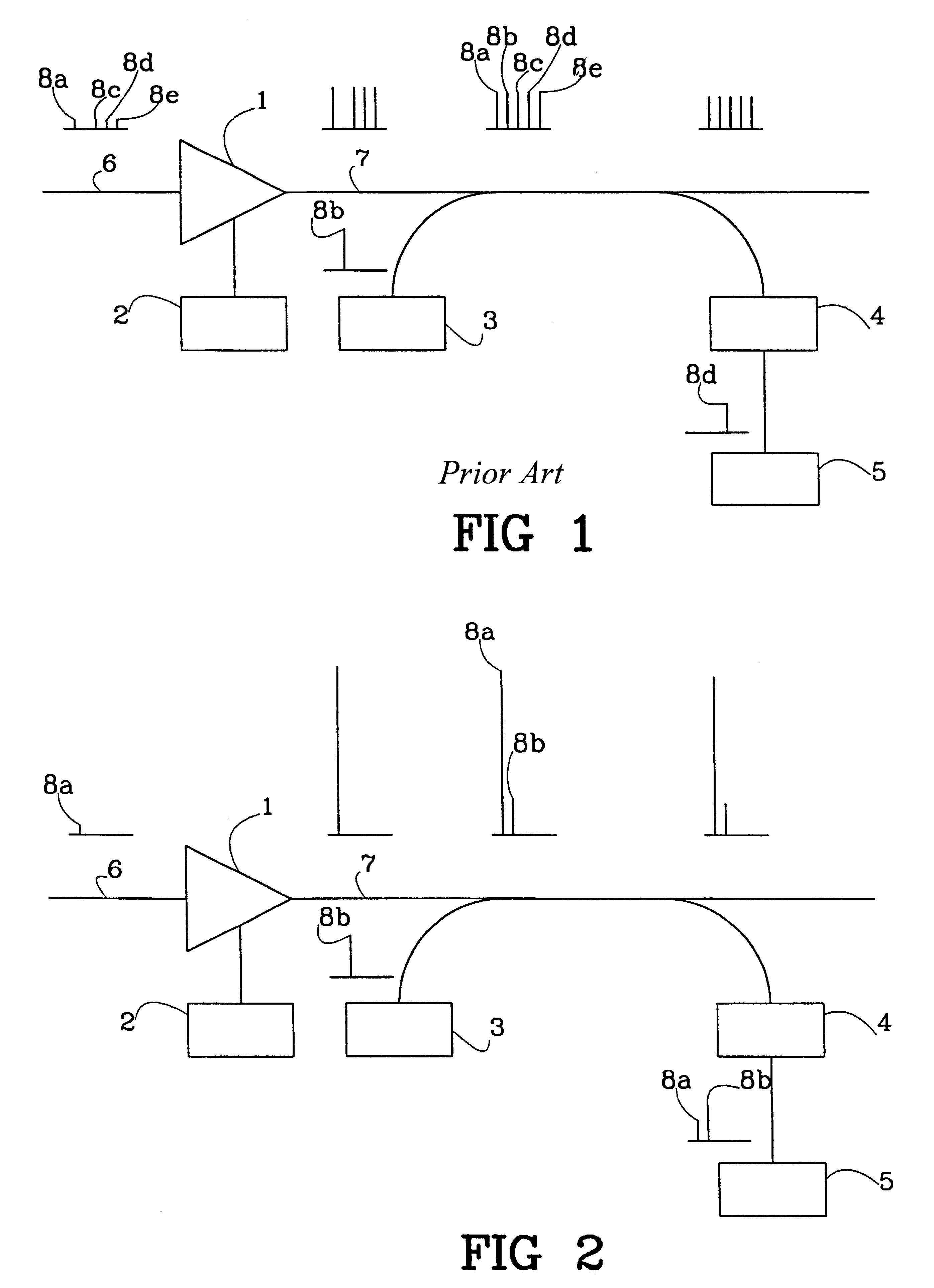
FIG. 1 shows in accordance with prior art an optical system optimised for five channels 8a, 8b, 8c, 8d and 8e using wavelength division multiplexing. The system can be part of the telephone system for example. In the optical system, an optical amplifier 1 has constant output power. The amplifier 1 is controlled by a pump laser 2. An optical fibre 6 leads into the amplifier 1 from other nodes in the system and an optical fibre 7 leads from the amplifier 1 to other nodes in the system. In the fibre 6, 7 channels can be added and dropped. In the example shown, four channels 8a, 8c, 8d, 8e come through the first fibre 6 into the amplifier 1, are amplified and exit in the second fibre 7. An additional channel 8b is thereafter added from a transmitter 3. All of the channels 8a, 8b, 8c, 8d, 8e will then be of the same strength and one selected cannel 8d can be read by a filter 4 selecting the specific wavelength of the selected channel 8d and sending it on to a receiver 5...


PUM


Abstract

A system and method for controlling the output power of an optical amplifier in a node in a network, wherein the output power of the amplifier is controlled via a pump laser in a control circuit. The node reads a supervisory channel comprising information on how to control the amplifier. The node then uses the information for the control of the amplifier.

Description

The present invention relates to a method for controlling the output power of optical amplifiers, particularly in nodes in a network, and to a node in a network.DESCRIPTION OF RELATED ARTWave Division Multiplexing (WDM) is a technology allowing the transmission of a number of optical signals through an optical fibre using different separated light wavelengths. In this way the information carrying capacity may be increased significantly. The capacity depends on the bandwidth of the channels and the number of used wavelength channels. The signal at each wavelength travels through the fibre irrespectful of the other signals, so that each signal represents a discrete channel with large bandwidth.When signals are sent long distances the signals have to be regenerated or optically amplified at intervals. An optical amplifier may comprise an erbiumdoped fibre that is being pumped by a high power semiconductor laser, here called "pump laser" for short.The optical amplifier differs from the ...

Claims


Application Information

Patent Timeline
Patent Type & Authority Patents(United States)
IPC IPC(8): H04B10/17H04J14/02H04B10/291H04B10/293H04B10/296H04J14/00
CPCH04B10/291H04B10/2918H04B10/296H04B10/2939H04J14/0221H04B2210/003H04B10/298
Inventor ASKINGER, TOMASJOHANSSON, BENGTWOOD, NIGEL ROBERT
Owner TELEFON AB LM ERICSSON (PUBL)
Why Eureka
Try Eureka