
Method, system and program for scrolling index scans

a scrolling index and scanning method technology, applied in the field of scrolling index scanning methods, systems and programs, can solve the problems of inefficiency of the process and the inability to move forward a large number of entries, and achieve the effect of minimizing the amount of traffic and minimizing the number of calls

Inactive Publication Date: 2003-11-25
IBM CORP
View PDF9 Cites 43 Cited by
  • Summary
  • Abstract
  • Description
  • Claims
  • Application Information

AI Technical Summary

Benefits of technology

Preferred embodiments provide a technique for scrolling a cursor forward and backward through a database object, such as an index or database table, in an efficient manner that minimizes the amount of traffic among the different database components. With preferred embodiments, the determination of whether index and / or base table entries satisfy cursor predicates is determined by the data manager and / or index manager components, thereby minimizing the number of calls that need to be performed to complete a fetch forward or backward operation with a dynamic cursor.
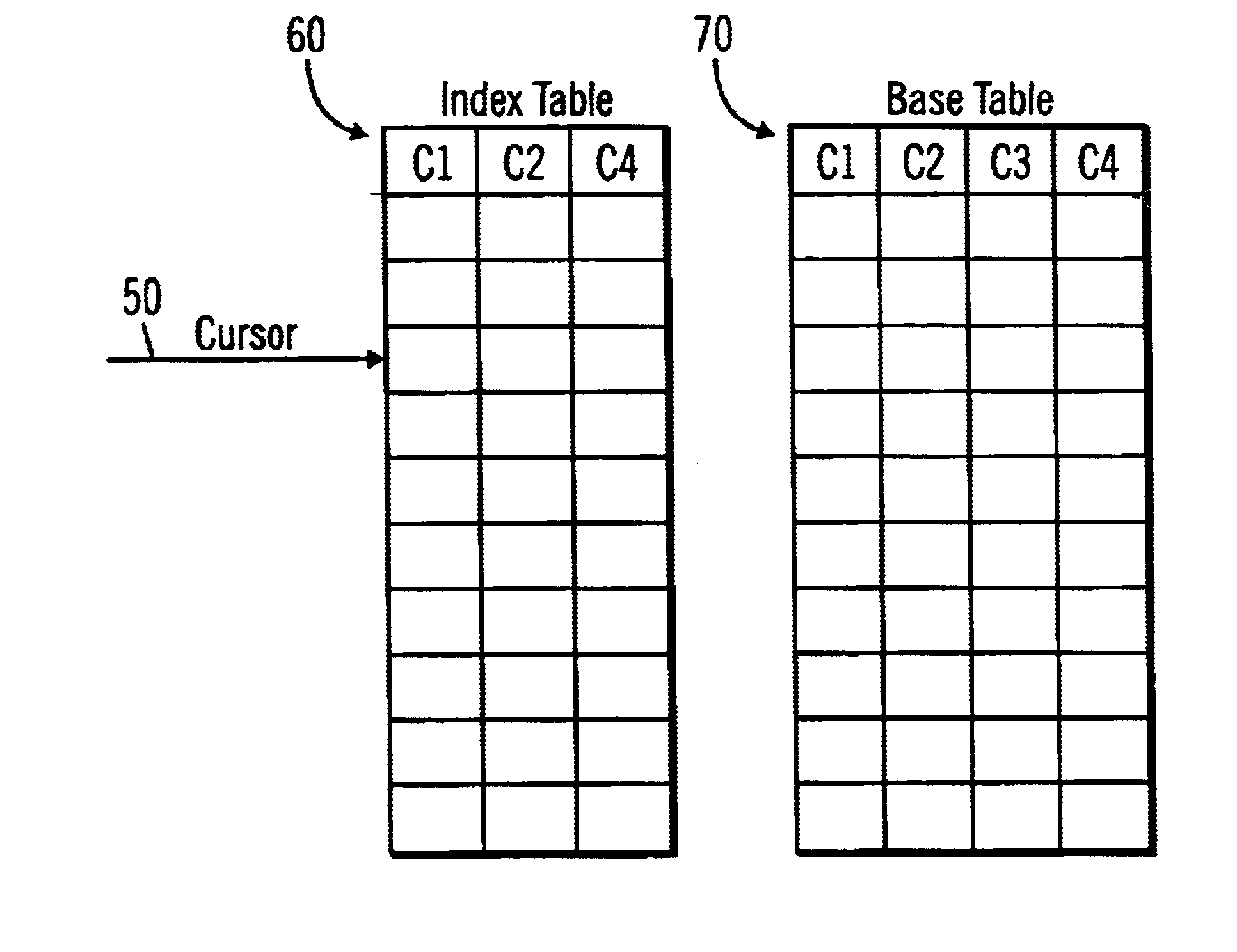
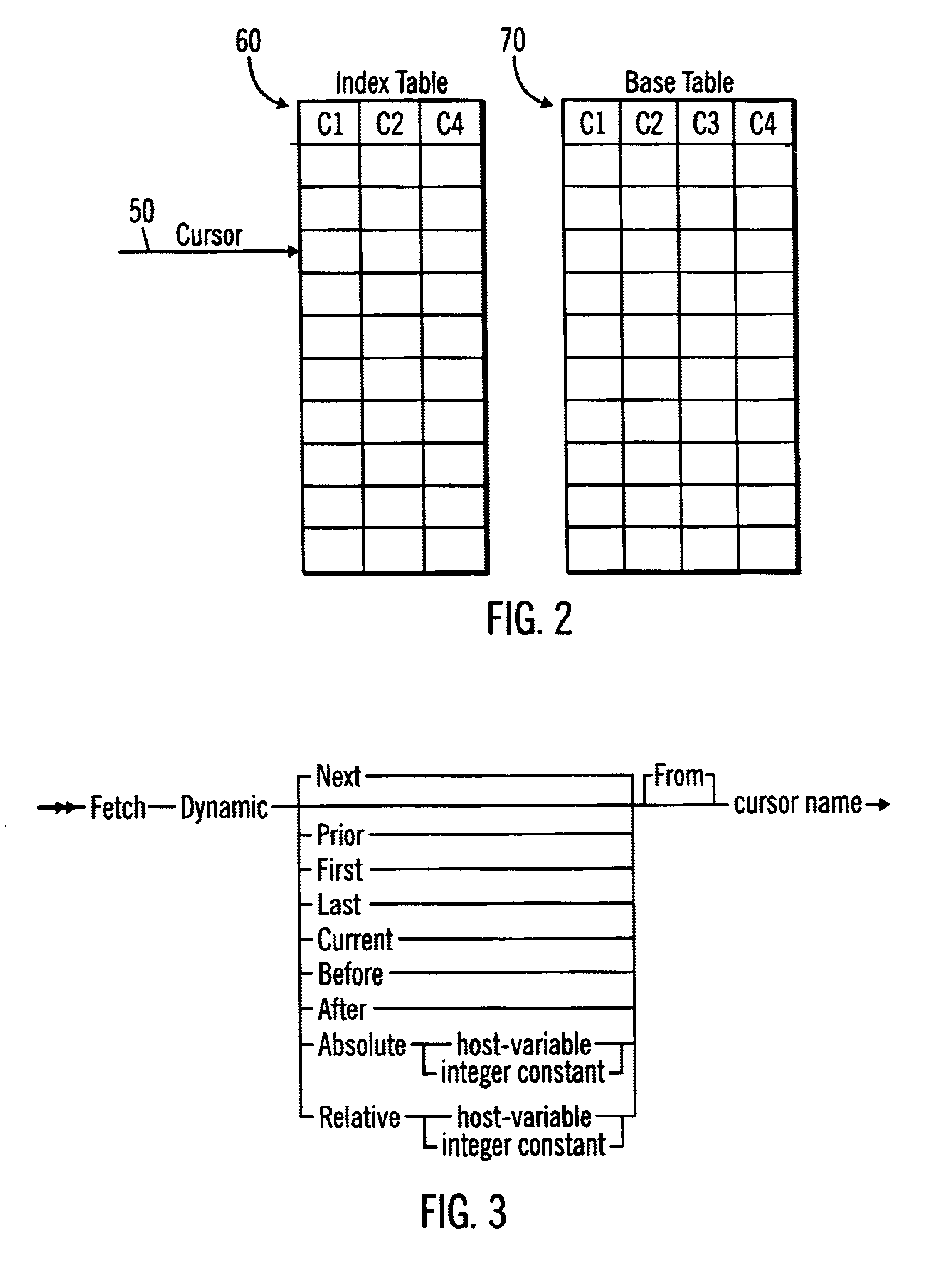
FIG. 2 illustrates how a cursor 50 points to rows in an index 60 including columns C1, C2, and C4 from database table 70. In a dynamic cursor, the cursor 50 points to rows in the database table 60 or index that satisfy the predicates. The application 2 would issue a DECLARE statement to initialize a cursor. The declaration would include a SELECT statement specifying columns of the index 60 or database table 70 and a WHERE clause including one or more predicates to qualify rows of the database table 70. The runtime component 14 would pass the DECLARE command to the data manager 16 to initialize the cursor 50 to point to the first qualifying row in the index 60. If there was no index 60 on the database table 70, then the cursor 50 would be initialized to point to the first qualifying row of the table 70. An index 60 provides for faster searching of the rows in the database table 70.
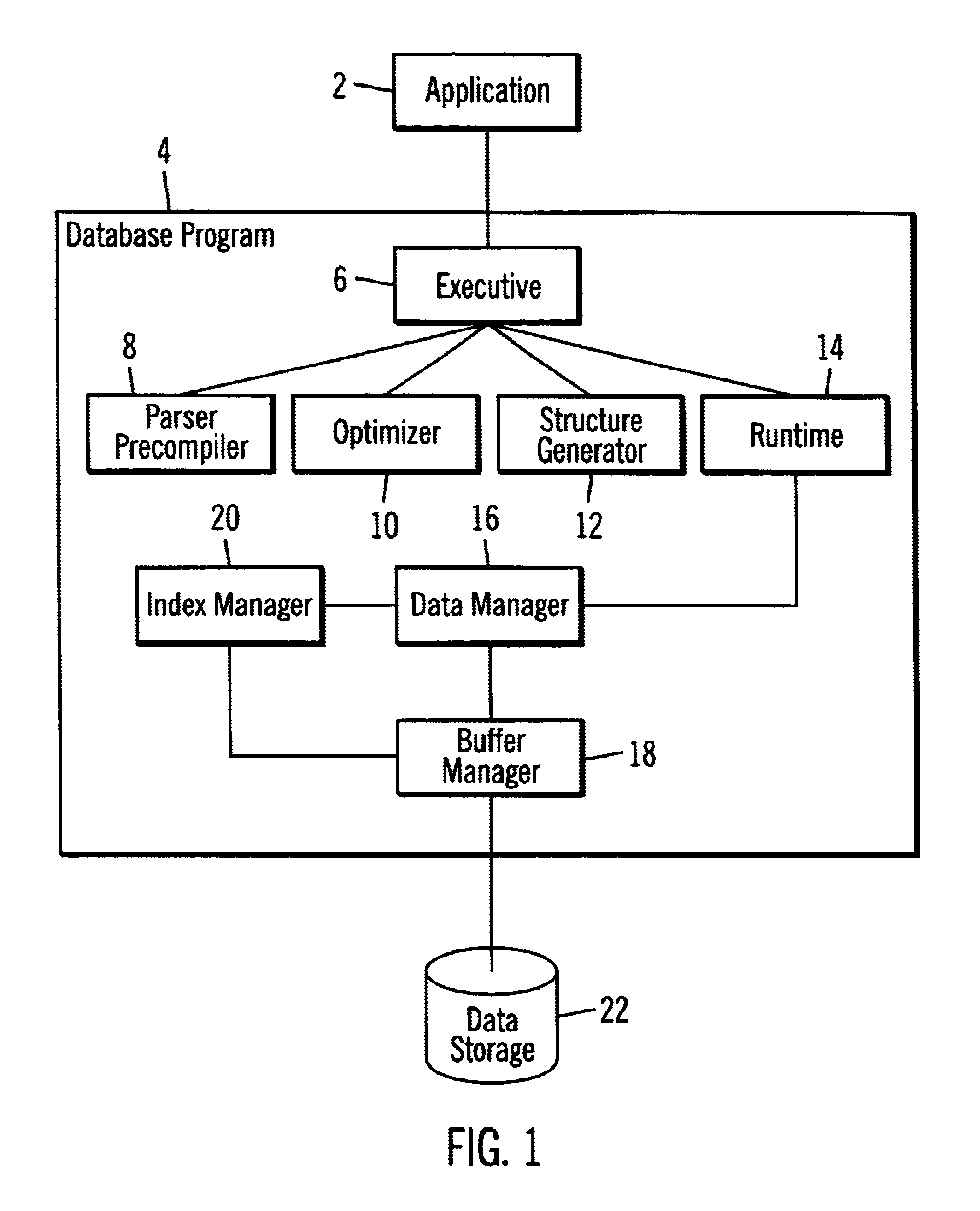
With the logic of FIGS. 4 and 5, the database program 4 implements dynamic scrollable cursors in a manner that minimizes the overhead of fetch related operations that occur among the runtime 14 and the data 16 and index 18 managers. With the preferred embodiments, the runtime 14 provides the data manager 16 the FETCH statement to scroll forward or backward k positions. The data manager 16 would call the index manager 20 to check the FETCH predicates against index columns. The index manager 16 would perform a qualifying operations to the extent possible. Only if the index manager 16 could not alone qualify rows, i.e., a partial qualification, such as the case if both index and non-index columns must qualify, then the index manager 20 would call the data manager 18 to qualify any non-index columns.
With the preferred embodiments, the runtime component that receives the commands from the application pushes down scrolling operations to the level of the manager component, such as the data manager 16 and index manager 20, that controls access to the database table or index where the scrolling occurs. In this way, the number of transactions and communications among the runtime component, data manager 16 and index manager 20 are minimized. Preferred embodiments improve performance of the scrolling index by eliminating the overhead of repeated calls from the runtime 14 and data manager 16 components by having the index manager 20 perform as many qualifying operations as possible.

Problems solved by technology

This process is inefficient because the cursor has to fetch through rows that have already processed.
This process can be quite slow to move forward a large number of entries because the runtime module must make numerous calls to a data manager module and index manager module to return each entry in the table or index and then determine whether the entries satisfy the predicates included in any WHERE statements provided with the cursor.

Method used


Image

  • Method, system and program for scrolling index scans
  • Method, system and program for scrolling index scans
  • Method, system and program for scrolling index scans

Examples


embodiments and conclusions

Alternative Embodiments and Conclusions

This concludes the description of the preferred embodiments of the invention. The following describes some alternative embodiments for accomplishing the present invention.

The preferred embodiments may be implemented as a method, apparatus or program using standard programming and / or engineering techniques to produce software, firmware, hardware, or any combination thereof. The programs and code defining the functions of the preferred embodiment can be delivered to a computer via a variety of information bearing media, which include, but are not limited to, computer-readable devices, firmware, programmable logic, memory devices (e.g., EEPROMs, ROMs, PROMs, RAMs, SRAMs, etc.) "floppy disk," CD-ROM, a file server providing access to the programs via a network transmission line, wireless transmission media, signals propagating through space, radio waves, infrared signals, etc. Still further the code in which the preferred embodiments are implemente...


PUM


Abstract

A method, system and program for accessing records in a database object, such as an index or table. A cursor is maintained that points to a start entry in the database object. The database object has rows and columns of values. A runtime component receives a command to return a kth entry in the object having column values that satisfy predicates in a query statement. The runtime component calls a manager component that accesses entries in the database object to return the kth entry in the object having column values that satisfy the predicates. The manager component moves the cursor through sequential entries in the database object, in either the forward or reverse direction, until a kth entry that satisfies the predicates from the start entry is reached. The manager component positions the cursor to an entry that is the kth entry that satisfies the predicates from the start entry and returns data from the kth entry pointed to by the cursor to the runtime component.

Description

BACKGROUND OF THE INVENTION1. Field of the InventionThe present invention relates to a method, system, and program for implementing scrollable cursors in a database program to perform backward and forward scans.2. Description of the Related ArtPrior art database programs include a feature referred to as cursors. A cursor is a named control structure used by an application program to point to a row of interest within some set of rows and to retrieve rows from the set, possibly making updates and deletions. A cursor points to rows from a database table that satisfy a structured query language (SQL) query against the table. The rows in the table that satisfy the SQL query comprise a result set of data. In dynamic cursors, the row is evaluated at the time it is fetched.When a cursor is opened or initialized, the current row position of the cursor is the first record or row in the table or index that satisfies the query. The application program may then issue fetch commands to move the c...

Claims


Application Information

Patent Timeline
IPC IPC(8): G06F17/30G06F3/00
CPCG06F17/30595Y10S715/968Y10S707/99933G06F16/284
Inventor HOLLINES, III, ROBERT J.LEE, CHRISTINA MARIELEVISH, DAVID L.PHOENIX, SAN YUSHADDUCK, MICHAEL R.
Owner IBM CORP
Learn More