Hitch-mounted pivotable racking assembly

a technology of racking assembly and pivoting plate, which is applied in the direction of supplementary fittings, travelling carriers, travelling articles, etc., can solve the problems of racking assembly collapse backwards, and achieve the effect of convenient securization and easy placement on the vehicl

Inactive Publication Date: 2003-12-02
VIGOR SPORTS
View PDF6 Cites 25 Cited by
  • Summary
  • Abstract
  • Description
  • Claims
  • Application Information

AI Technical Summary

Benefits of technology

In one embodiment, the upper end of one of the frame support members curves inward toward the upper end of the other frame support member near the equipment support assembly. This results in the spacing between the ends of the frame support members being greater at the hitch mount than at the equipment support assembly. That is, the frame support members are positioned more closely together at the equipment support assembly than at the hitch mount. This configuration allows the pivotable racking assembly to collapse backward away from a person as equipment is placed on top of the equipment support assembly. When the racking assembly is mounted on the rear of a car, for example, this difference permits the racking assembly to rotate backward toward the vehicle when weight is applied to the racking assembly.
The configuration of the upper ends of the frame support members allows a person to safely place equipment onto the racking assembly without the possibility of accidentally collapsing the racking assembly toward himself or herself. As equipment is placed onto the equipment support bars connected to the equipment support assembly, the weight of the equipment forces the frame support members to pivot relative to the hitch member and equipment support assembly such that the racking assembly falls backward away from the user. As a force is applied to the equipment support bars, the force is transferred to the frame support members by the curvature of the upper end of one of the frame support members and the smaller difference in distance between the two frame support members at the upper ends than at the lower ends. The racking assembly pivots around a locking pin coupling the curved frame support member to the equipment support assembly, and the applied force is distributed between the longitudinal axis of the second frame support member and the pivot point of the first frame support member. This causes the frame support members to pivot away from the application of the force, and therefore it is the curvature of the upper end of the frame support that causes the racking assembly to collapse backwards away from a user standing adjacent to the equipment support bars.
In another embodiment, the second frame support member includes a pair of tubes of the same length and curvature welded together. This configuration provides additional security for the entire racking assembly and more support for items place on the equipment support assembly.
Accordingly, one object of the present invention is to provide a racking assembly that falls away from a person loading equipment onto the racking assembly. It is another object of the present invention to provide a racking assembly that is easily securable to prevent equipment from falling from the racking assembly. It is further an object of the present invention to provide a racking assembly that is easily placeable onto a vehicle to transport or store equipment.

Problems solved by technology

This causes the frame support members to pivot away from the application of the force, and therefore it is the curvature of the upper end of the frame support that causes the racking assembly to collapse backwards away from a user standing adjacent to the equipment support bars.

Method used


Image

  • Hitch-mounted pivotable racking assembly
  • Hitch-mounted pivotable racking assembly
  • Hitch-mounted pivotable racking assembly

Examples


Embodiment Construction

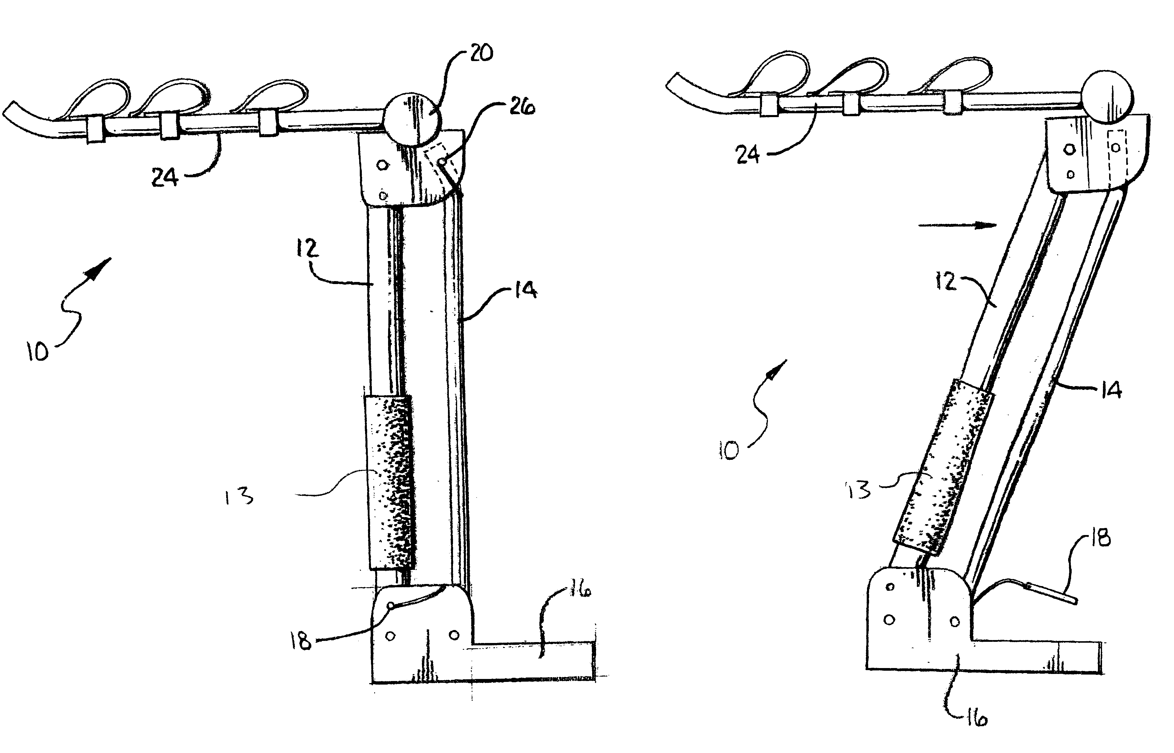
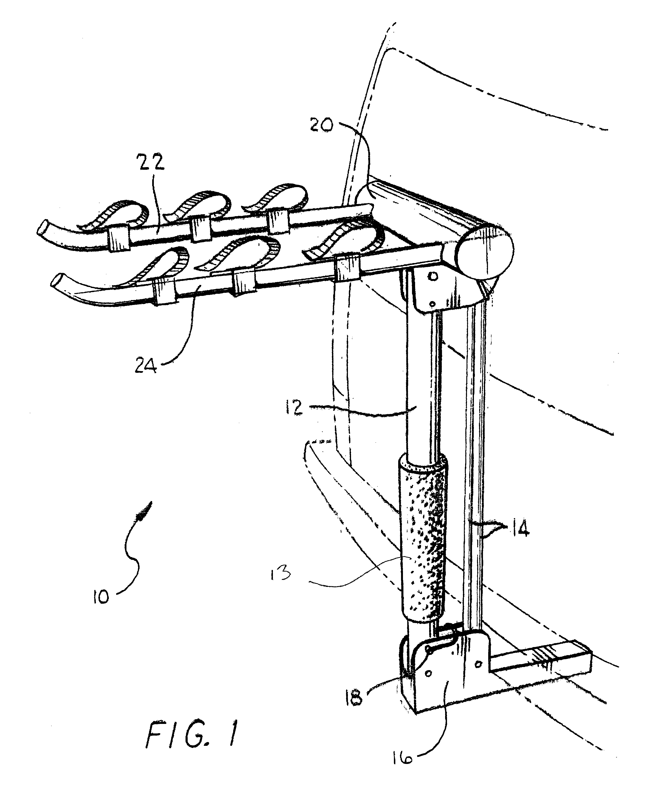
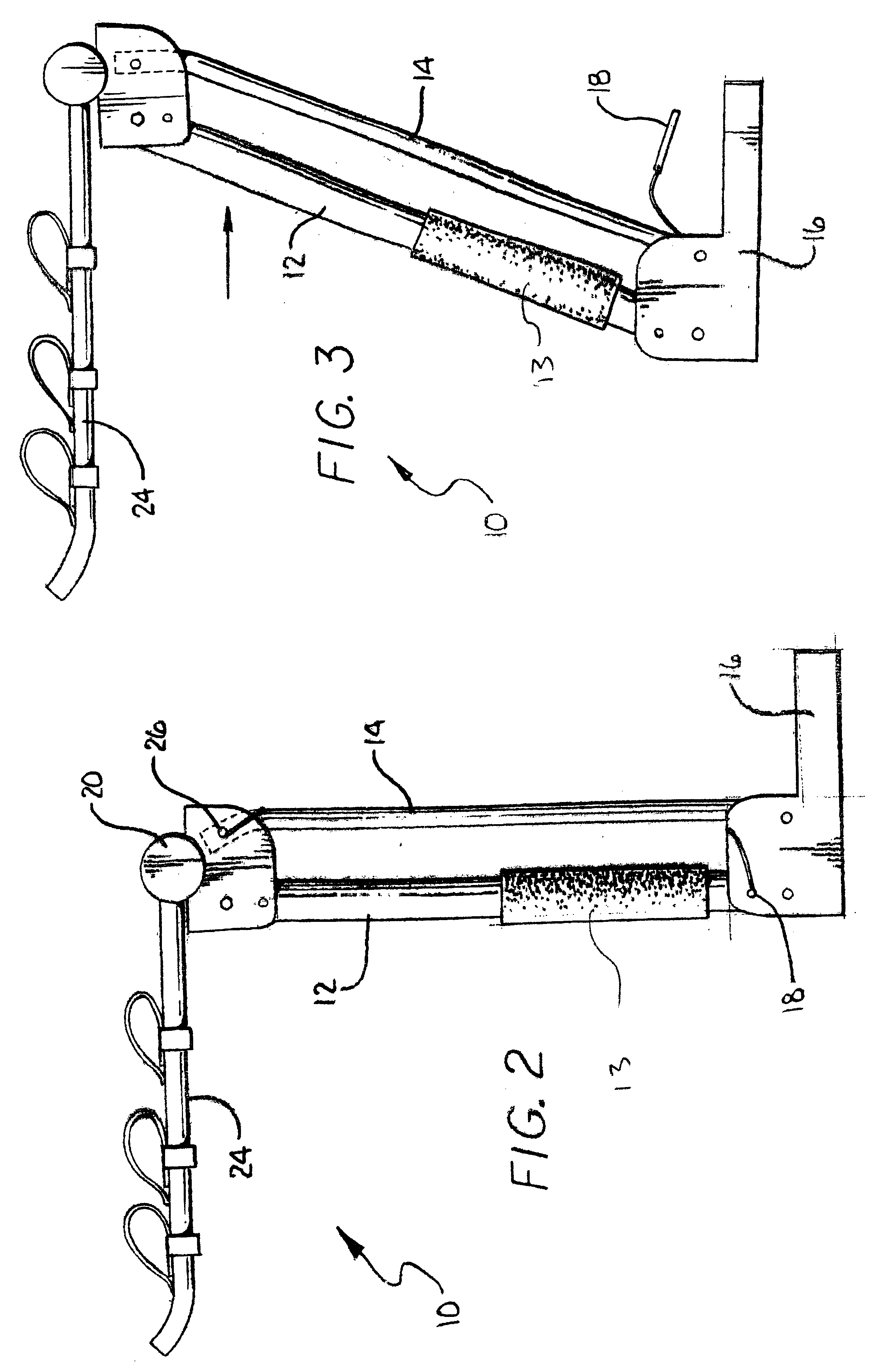
A racking assembly 10 of the present invention is articulable from a generally upright position, shown in FIG. 1, to a variety of declined positions as shown in FIGS. 2-6. The racking assembly 10 is mountable to a hitch of a vehicle, and when so mounted, enables equipment of various types to be carried thereon. Although the invention is generally described in the context of providing a rack for carrying bicycles, it is to be understood that the racking assembly is equally suited for carrying other types of equipment or articles, among which are included but not limited to surf boards, kayaks, canoes, skis, and luggage.

Both frame support members are generally tubular and constructed from a durable metal such as extruded steel, although any suitable material which is able to withstand the demands of an equipment-carrying, vehicle mounted racking assembly may be used. Such materials should possess sufficient strength characteristics so that various types of equipment, which often might...


PUM


Abstract

A racking assembly for securely storing and transporting recreational equipment on vehicles includes a hitch mount, an equipment support assembly, and pair of support members having lower ends pivotally coupled to the hitch mount and upper ends pivotally coupled to the equipment support assembly. The support members are configured to allow the racking assembly to collapse away from a user placing equipment thereon so that injury is prevented from the weight of the equipment causing the racking assembly to collapse onto a user.

Description

1. Field of the InventionThe invention relates generally to racking assemblies. Specifically, the invention relates to racking assemblies capable of being mounted onto hitch attachments of vehicles to transport equipment, such as bicycles, skis and luggage.2. General Background and State of the ArtThere are many prior art racking assemblies capable of securely holding articles while being mounted on vehicles. Some prior art racking assemblies are capable of attaching to the rear of vehicles having a hitch. These prior art racking assemblies are placed on vehicles by positioning the racking assembly onto the hitch and locking the racking assembly in place using a pin. When the pin is in place, the racking assembly cannot move forward or backward relative to the vehicle, thereby providing a secure assembly for transporting a variety of articles. However, as the vehicle moves, unstable movement of the racking assembly may occur. Movement of the vehicle, especially at high speeds, may c...

Claims


Application Information

Patent Timeline
Patent Type & Authority Patents(United States)
IPC IPC(8): B60R9/06B60R9/00
CPCB60R9/06Y10S224/924
Inventor JEONG, CHANYOUNG
Owner VIGOR SPORTS
Why Eureka
Try Eureka