
Laminated glass and glass plate used for producing laminated glass

a technology of laminated glass and glass plate, which is applied in the direction of glass tempering apparatus, roof, synthetic resin layered products, etc., can solve the problems of he or she may give up the criminal act, the principal stress itself cannot be directly measured, and the laminated glass cannot be easily penetrated

Inactive Publication Date: 2003-12-02
ASAHI GLASS CO LTD
View PDF10 Cites 23 Cited by
  • Summary
  • Abstract
  • Description
  • Claims
  • Application Information

AI Technical Summary

Problems solved by technology

Accordingly, even if crushing to the laminated glass is attempted by knocking it with a blunt instrument, the laminated glass can not easily be penetrated because the interlayer has stretching properties.
If the invasion is not successful in a short time, he or they may give up the criminal act.
However, the principal stress itself can not directly be measured.
However, the glass plate having a strength of 35 MPa or more is hardly broken when a human body hits the glass plate in car crushing or the like, and the glass plate may not absorb sufficiently the impact force whereby the human body may be damaged.
In the above-mentioned publications, however, there is no disclosure of a glass plate and a laminated glass satisfying these conditions.

Method used


Image

  • Laminated glass and glass plate used for producing laminated glass
  • Laminated glass and glass plate used for producing laminated glass
  • Laminated glass and glass plate used for producing laminated glass

Examples


Embodiment Construction

Now, the present invention will be described in further detail with reference to Examples. However, it should be understood that the present invention is by no means restricted to such specific Examples.

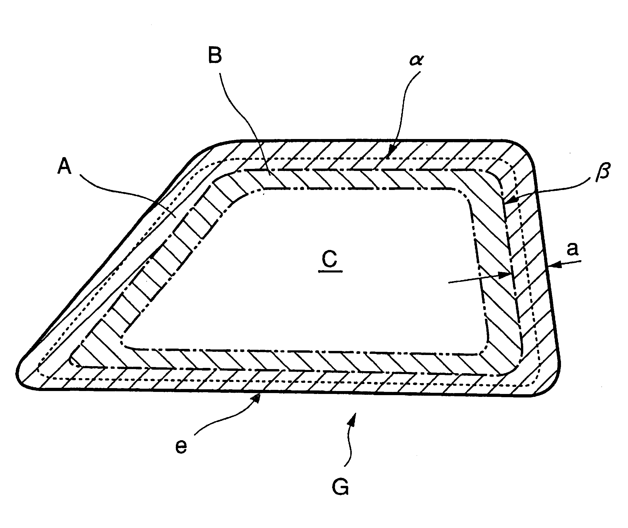
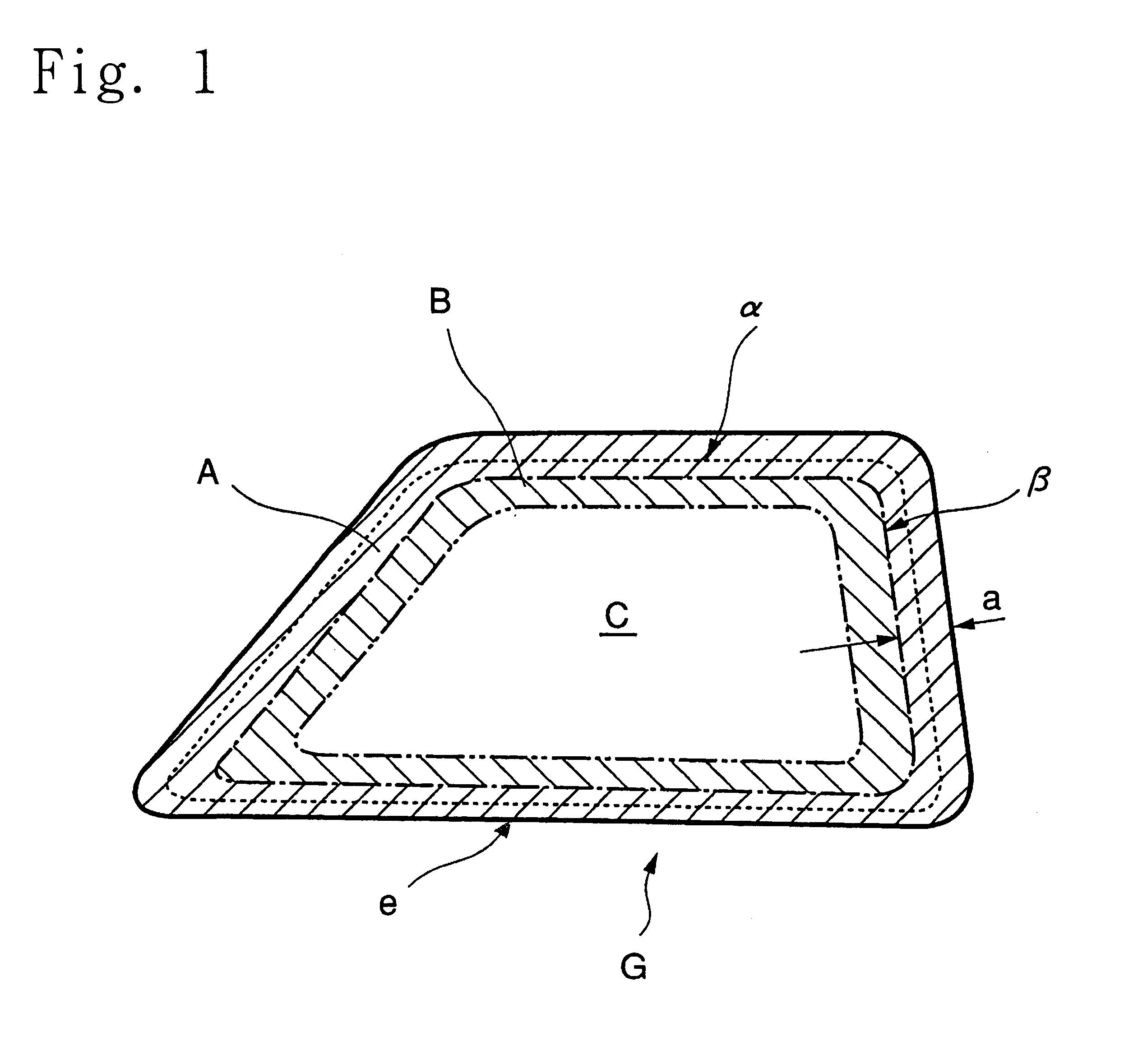
FIG. 5 is a front view showing diagrammatically the glass plate of the present invention wherein a left side in the paper surface of the figure corresponds to a front side of the glass plate in a state of being assembled in an automobile. The dimensions of the glass plate were determined so that the length of an upper side L.sub.1 =600 mm, the length of a lower side L.sub.2 =800 mm, the height H=550 mm and the thickness=2.2 mm. A point indicated by P.sub.a1 is a point on the center line .alpha., which is the middle point between a front side corner portion of the upper side of the glass plate G and a front side corner portion of the upper side of the border line .beta.. A line through point P.sub.a1 which is perpendicular to a line tangent to the edge portion e, a line tangent to the...


PUM

PropertyMeasurementUnit
widthaaaaaaaaaa
particle sizeaaaaaaaaaa
thicknessaaaaaaaaaa

Abstract

A glass plate has a thickness of from 1.5 to 3 mm, and it has a peripheral region having a predetermined width along the edge line of the plate and having its principal stress difference of compressive properties, an intermediate region having a predetermined width adjacent to an inner periphery of the peripheral region and having its principal stress difference of tensile properties and a central region occupying an inner peripheral side of the intermediate region wherein the central region has an averaged surface compression stress of from 15 to 35 MPa, and the peripheral region has a width of from 5 to 20 mm; the maximum value of the principal stress difference averaged in a thickness direction of the plate along its center line is from 20 to 40 MPa, and the minimum value of the principal stress difference averaged in a thickness direction along the center line is from 8 to 25 MPa.

Description

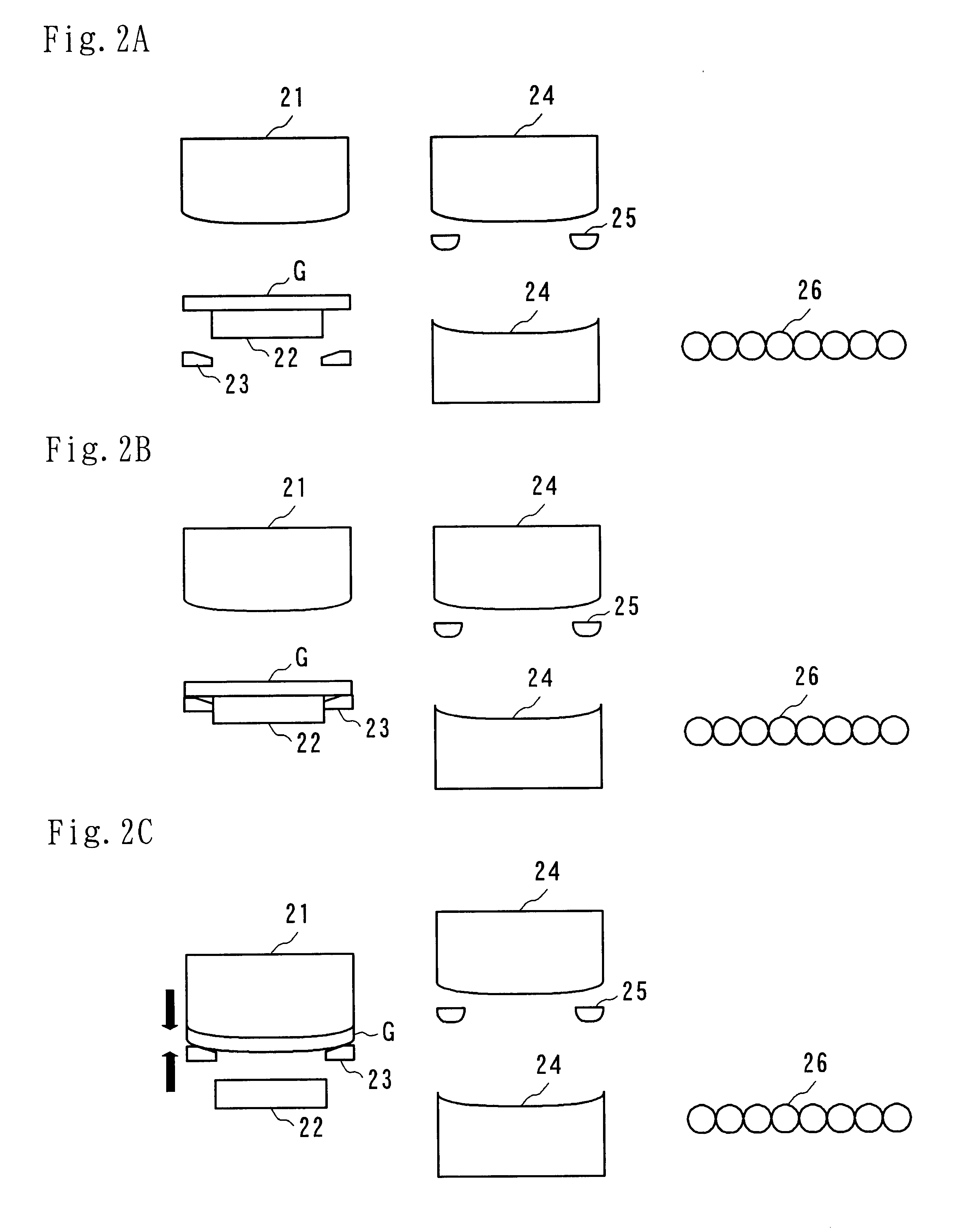
DISCUSSION OF BACKGROUNDThe present invention relates to a laminated glass and a glass plate used for producing the laminated glass.Heretofore, tempered glass has mainly been used, in a form of single plate, for a shielding window of automobiles. In recent years, however, laminated glass has been used because of its having good security performance and sound insulating properties. The laminated glass is prepared by interposing an interlayer made of polyvinylbutyral or the like between two glass plates and bonding them. Accordingly, even if crushing to the laminated glass is attempted by knocking it with a blunt instrument, the laminated glass can not easily be penetrated because the interlayer has stretching properties. A criminal actor or actors of car such as robbery or burglar often break a window glass, unlock the door and invade into the cabin. If the invasion is not successful in a short time, he or they may give up the criminal act. Accordingly, it will be effective to use th...

Claims


Application Information

Patent Timeline
Patent Type & Authority Patents(United States)
IPC IPC(8): B32B17/10B32B17/06C03B27/04C03B27/044C03B27/004C03B27/00C03C23/00C03C17/00
CPCB32B17/10036C03B27/004C03B27/0413C03B27/0442C03C17/007C03C23/007B32B17/10091B32B17/10981Y10T428/24926C03C2217/476C03C2217/479Y10T428/24777Y10T428/24992Y10T428/256Y10T428/2495B32B17/10633Y10T428/31623
Inventor TAKAHARA, MASAYUKI
Owner ASAHI GLASS CO LTD
Learn More