Method for preparing integral turbine blade disc based on SiC fiber ceramic matrix composite material
A technology of turbine blisks and composite materials, which is applied in mechanical equipment, blade support elements, engine elements, etc., can solve problems such as poor practicability, and achieve the effects of good practicability, high-density preparation, and shortened preparation cycle.
- Summary
- Abstract
- Description
- Claims
- Application Information
AI Technical Summary
Problems solved by technology
Method used
Image
Examples
Embodiment 1
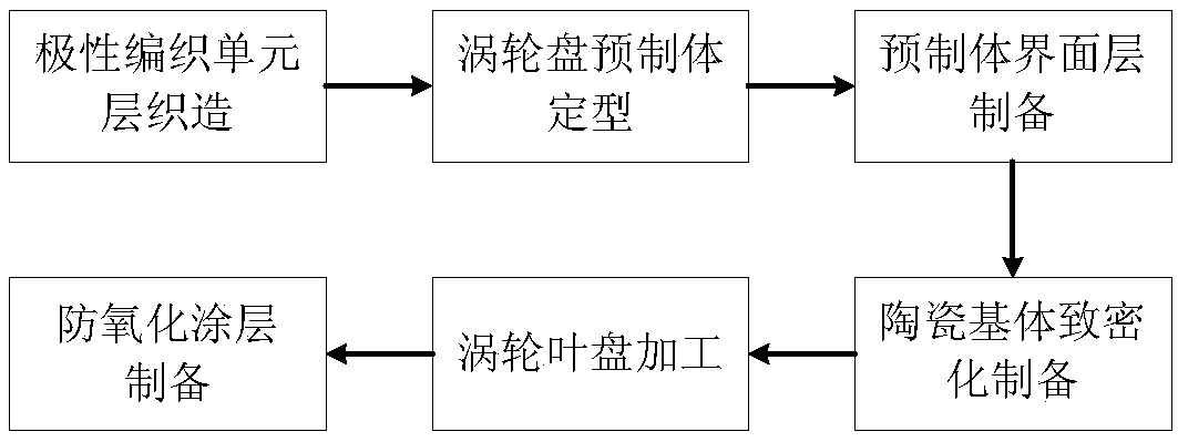
[0020] (1) Using SiC fibers as raw materials, place the warp SiC fibers at equiangular intervals with the origin of the polar coordinates as the center of the circle, and finally form a circular warp fiber arrangement, and the end of each warp fiber is fixed in the ring by elastic leads. On the tooling, the warp fiber arrangement density is designed according to the target load.
[0021] Starting from the center of the circle, the latitudinal SiC fibers are interwoven up and down with two bundles of adjacent meridional fibers, and are wound continuously outward one by one in the circumferential direction. The weft fiber winding density is designed according to the target load.
[0022] As the number of weft fiber rings increases, the angle between two warp fibers gradually increases, and yarn is evenly added at the angle between two adjacent warp fibers to ensure the local volume fraction of warp and weft fibers in the fabric. Consistently until the desired diameter circular f...
Embodiment 2
[0031] (1) Using SiC fibers as raw materials, place the warp SiC fibers at equiangular intervals with the origin of the polar coordinates as the center of the circle, and finally form a circular warp fiber arrangement, and the end of each warp fiber is fixed in the ring by elastic leads. On the tooling, the warp fiber arrangement density is designed according to the target load.
[0032] Starting from the center of the circle, the latitudinal SiC fibers are interwoven up and down with two bundles of adjacent meridional fibers, and are wound continuously outward one by one in the circumferential direction. The weft fiber winding density is designed according to the target load.
[0033] As the number of weft fiber rings increases, the angle between two warp fibers gradually increases, and yarn is evenly added at the angle between two adjacent warp fibers to ensure the local volume fraction of warp and weft fibers in the fabric. Consistently until the desired diameter circular f...
Embodiment 3
[0042] (1) Using SiC fibers as raw materials, place the warp SiC fibers at equiangular intervals with the origin of the polar coordinates as the center of the circle, and finally form a circular warp fiber arrangement, and the end of each warp fiber is fixed in the ring by elastic leads. On the tooling, the warp fiber arrangement density is designed according to the target load.
[0043] Starting from the center of the circle, the latitudinal SiC fibers are interwoven up and down with two bundles of adjacent meridional fibers, and are wound continuously outward one by one in the circumferential direction. The weft fiber winding density is designed according to the target load.
[0044] As the number of weft fiber rings increases, the angle between two warp fibers gradually increases, and yarn is evenly added at the angle between two adjacent warp fibers to ensure the local volume fraction of warp and weft fibers in the fabric. Consistently until the desired diameter circular f...
PUM
| Property | Measurement | Unit |
|---|---|---|
| Density | aaaaa | aaaaa |
| Density | aaaaa | aaaaa |
| Breaking strength | aaaaa | aaaaa |
Abstract
Description
Claims
Application Information
 - R&D
- Intellectual Property
- Life Sciences
- Materials
- Tech Scout
- Unparalleled Data Quality
- Higher Quality Content
- 60% Fewer Hallucinations
Browse by: Latest US Patents, China's latest patents, Technical Efficacy Thesaurus, Application Domain, Technology Topic, Popular Technical Reports.
© 2025 PatSnap. All rights reserved.Legal|Privacy policy|Modern Slavery Act Transparency Statement|Sitemap|About US| Contact US: help@patsnap.com

