Sanding block

a technology of sanding block and sanding block, which is applied in the direction of gear teeth, manufacturing tools, manufacturing apparatus, etc., can solve the problems of inability to improve, inconvenient use, and inability to fix screws or nails,

Inactive Publication Date: 2003-12-09
LEVEL 5 TOOLS LLC +1
View PDF12 Cites 30 Cited by
  • Summary
  • Abstract
  • Description
  • Claims
  • Application Information

AI Technical Summary

Problems solved by technology

This attachment by screws or nails is inherently damaging to the drywall material.
Additionally, where the individual rectangles of drywall intersect in their attachment to walls and ceilings, there exists naturally a seam or void between the two adjoining drywall pieces.
Such sandpaper holding devices are conventionally known as sanding blocks and have not really improved over time.
Such conventional sanding blocks have inherent problems which cause excessive time usage due to fumbling during installation of the sandpaper.
Further, the use of such a biased clip device to hold the sand paper on the sanding block impedes the angles at which the elongated handle attached to the rear surface of the sanding block may achieve.
Still further, such conventional sanding blocks, because of their poor engagement between the sanding block and the attached pole or handle used to move them, are inherently prone to flipping over, wherein the biased clips and handle attachment can severely mar or dent the surface which is being finished thereby causing damage, lost time due to resurfacing requirements, as well as the potential need to replace the surface so damaged when working with expensive woods and exotic surface materials which cannot be covered over with paint and other surface materials.
Additionally, conventional sanding blocks have an inherent tendency to mar and scar the adjoining surfaces when the sanding block reaches the intersection of such surfaces.
Consequently, when sanding a ceiling, the adjoining wall surfaces frequently suffer damage from the sanding block upon the wall surfaces and vice versa.
However, Sanchez uses screw mounts which attach the sandpaper over the rear side which impede the angles at which the handle may reach in relation to the rear surface.
Additionally, Sanchez lacks the rotating attachment of the handle to the sanding block to aid in the prevention of sanding block flipover and adjacent surface marring, and teaches an expensive and complicated sealed engagement of the handle.
U.S. Pat. No. 5,895,316 (Williams) discloses a dry wall corner sander for use with a handle; however, Williams is only designed for sanding a curved surface and by design is intended to rock during use and would be extremely prone to flip over on a flat surface due to the high mounting point of the handle to the rear.
Brown, while disclosing a mount for the sanding block on the end of a pole, obstructs the pole from achieving a descending angle toward the leading edges by using mechanical mounts for the sandpaper also impedes the sideways transition of the pole due to the required vacuum accommodating mount of the pole to the back side of the sanding block.

Method used


Image

  • Sanding block
  • Sanding block
  • Sanding block

Examples


Embodiment Construction

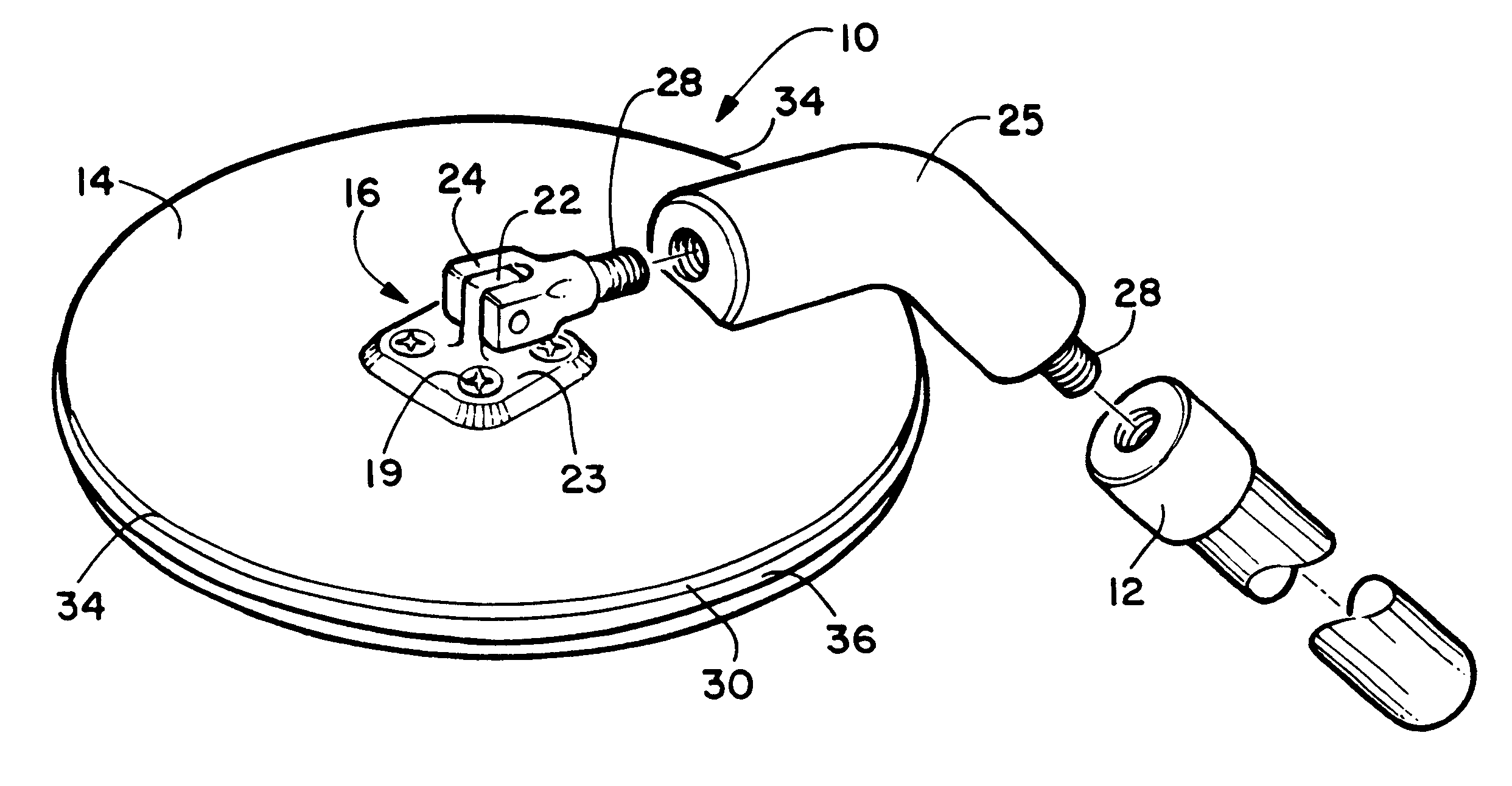
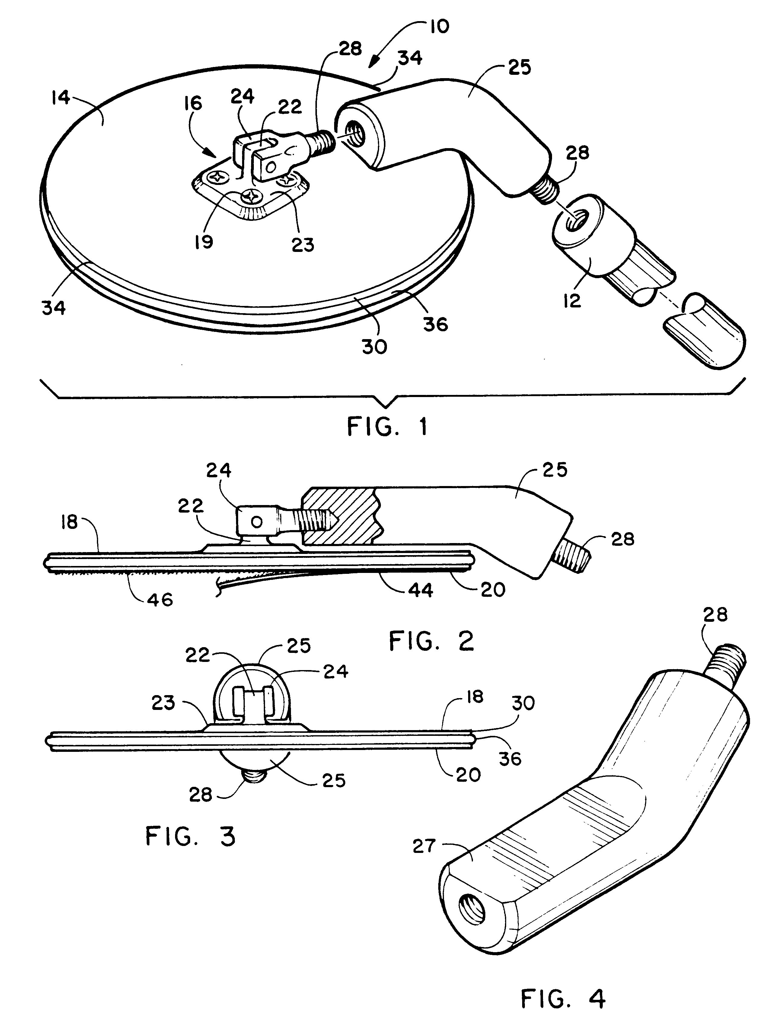
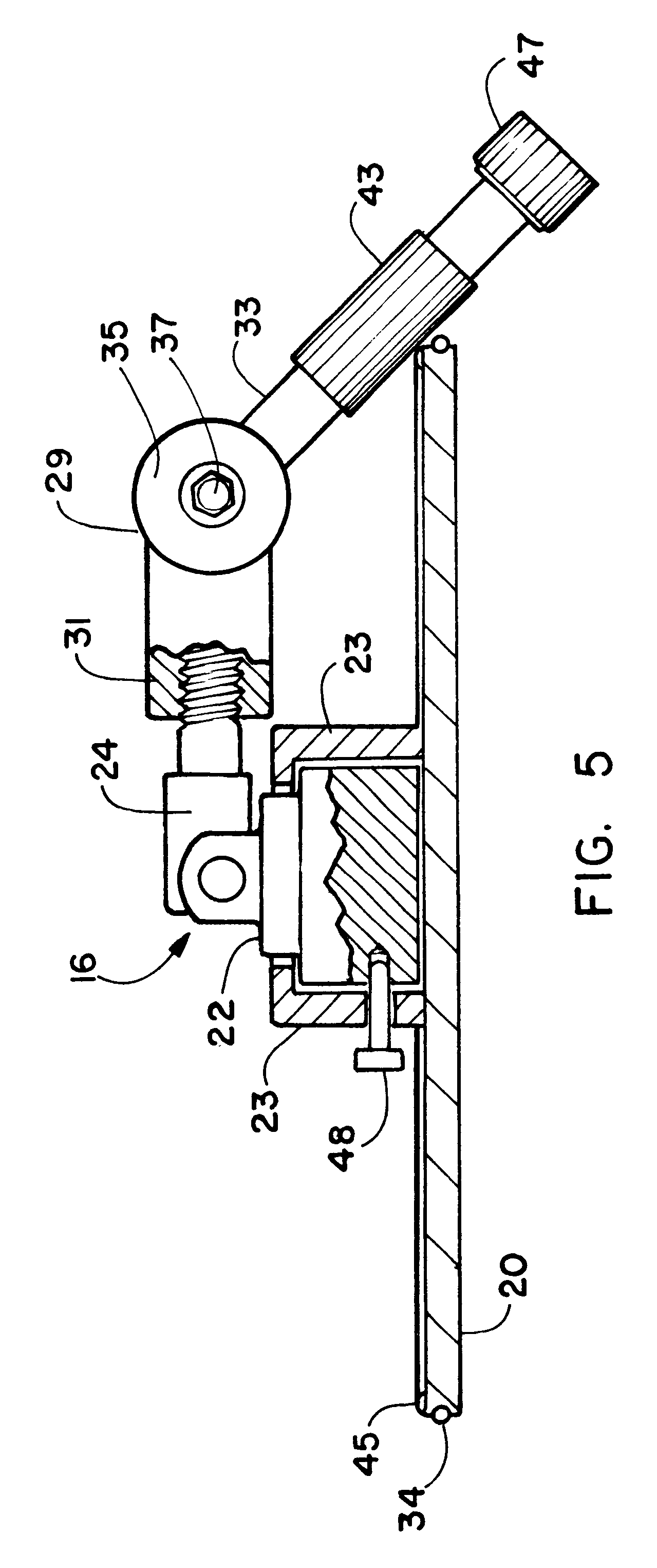
Referring now to the drawings FIGS. 1-5 disclose the preferred embodiments of the herein disclosed sanding block device 10 for attachment to, and use in combination with, an attachable pole 12 shown in phantom line.

In a first preferred embodiment as shown in FIG. 1 a sanding block 14 is round in shape. As used in this embodiment and all preferred embodiments herein, a pole mount 16 is affixed to the rear surface 18 opposite the working surface 20 of the generally planer sanding block 14.

The pole mount 16, in the current best mode, features an axle 22 rotationally engaged with a base 23 which is engaged with means of attachment to the rear surface 18 of the sanding block 14 which in this case is screws 19. The axle 22 has a center axis which is substantially normal to the rear surface 18 of the sanding block 14 however it could also be angled and such is anticipated.

Rotationally engaged with the axle 22 is a hub 24. The hub 24 thus engaged at a first end, has an attachment end that p...


PUM


Abstract

An improved sanding block for sanding high and extended surfaces configured for use in combination with an attached pole. The sanding block is round in shape and is rotationally mounted on a pole mount that interfaces between the sanding block and the pole which attaches to a rotatable hub of the pole mount. This allows the sanding block to rotate during use and the pole to be rotated to different angles in relation to the flat working surface of the sanding block. Adjacent surface marring is prevented by the rotation of the sanding block upon contact of a side edge with such an adjacent surface. Optionally the pole mount can be locked to prevent rotation if desired and a barrel can provide an interface between the pole and the pole mount. This barrel can be straight, angled, or adjustable for angle, in the different preferred embodiments.

Description

1. Field of the InventionThe present invention relates to a sanding block for surface preparation. More particularly it relates to an improved sanding block which is round and rotatably mounted on a swiveling attachment member which is cooperatively engageable with the distal end of an elongated pole.The device in the current best mode, also features an improved attachment of the handle to the rear surface of the sanding block which uses an angled or adjustable barrel providing for an angled engagement of the pole with the attachment member. This unique attachment provides for the user to easily sand using the extension handle at one or a plurality of angles of the handle to its attachment to the rear surface of the sanding block. Using this angled means of attachment provides the ability of sanding a surface at virtually any angle including a declining angle that allows for sanding of a horizontal surface, such as a ceiling, from underneath a ledge. Still further, the provision of ...

Claims


Application Information

Patent Timeline
Patent Type & Authority Patents(United States)
IPC IPC(8): B24D15/00B24D15/04B23F21/03B24B7/18B24D15/02
CPCB24B7/18B24D15/04B24D15/023B24B7/184
Inventor WETTSTEIN, BRAD R.HASSLER, JAMESDODDS, STEVE
Owner LEVEL 5 TOOLS LLC
Why Eureka
Try Eureka