Toilet cleaning dispenser system with removable cartridge

a technology of cleaning dispenser and cartridge, which is applied in the direction of water installation, lavatory sanitory, construction, etc., can solve the problems of waste of cleaning agents, messy and undesirable manual replacement, and damage to the plumbing of the toilet tank

Inactive Publication Date: 2003-12-16
FLUIDMASTER
View PDF15 Cites 41 Cited by
  • Summary
  • Abstract
  • Description
  • Claims
  • Application Information

AI Technical Summary

Benefits of technology

, a toilet cleaning dispenser system adapted for placement in a toilet tank includes a hanger, a dispenser housing and a cartridge device removably coupled to the dispenser housing. The cartridge device, which includes a cleanser tablet enclosed within a cartridge housing, is inserted into a cavity of the dispenser housing and turned in one direction to lock the device and, alternatively, in an opposite direction to unlock the device. The cartridge housing may be formed to turn as one unit, or be formed as a basket and a rotatable cap that can be turned with respect to the basket. The dispenser housing includes an inlet water trap and an outlet water trap, each comprising a pair of concentric, nested tubes that retain liquid after flushing so as to prevent fumes from exiting the dispenser housing into the toilet tank.

Problems solved by technology

Since the supporting means is located in the toilet bowl, manually replacement can be messy and undesirable.
This results in the release of fumes and various other gases which can cause damage to the plumbing of toilet tank.
As a result, much of the cleaning agent is wasted, thereby requiring frequent replacement.
Cleaning agents, provided in the form of cleanser tablets, for example, may contain chemicals which are harmful upon direct contact with human skin and eyes.
Furthermore, common cleanser tablets which are often brightly colored may tempt younger children to touch or even ingest the cleaning agent, especially if placed in the toilet bowl where a child can gain access.

Method used


Image

  • Toilet cleaning dispenser system with removable cartridge
  • Toilet cleaning dispenser system with removable cartridge
  • Toilet cleaning dispenser system with removable cartridge

Examples


Embodiment Construction

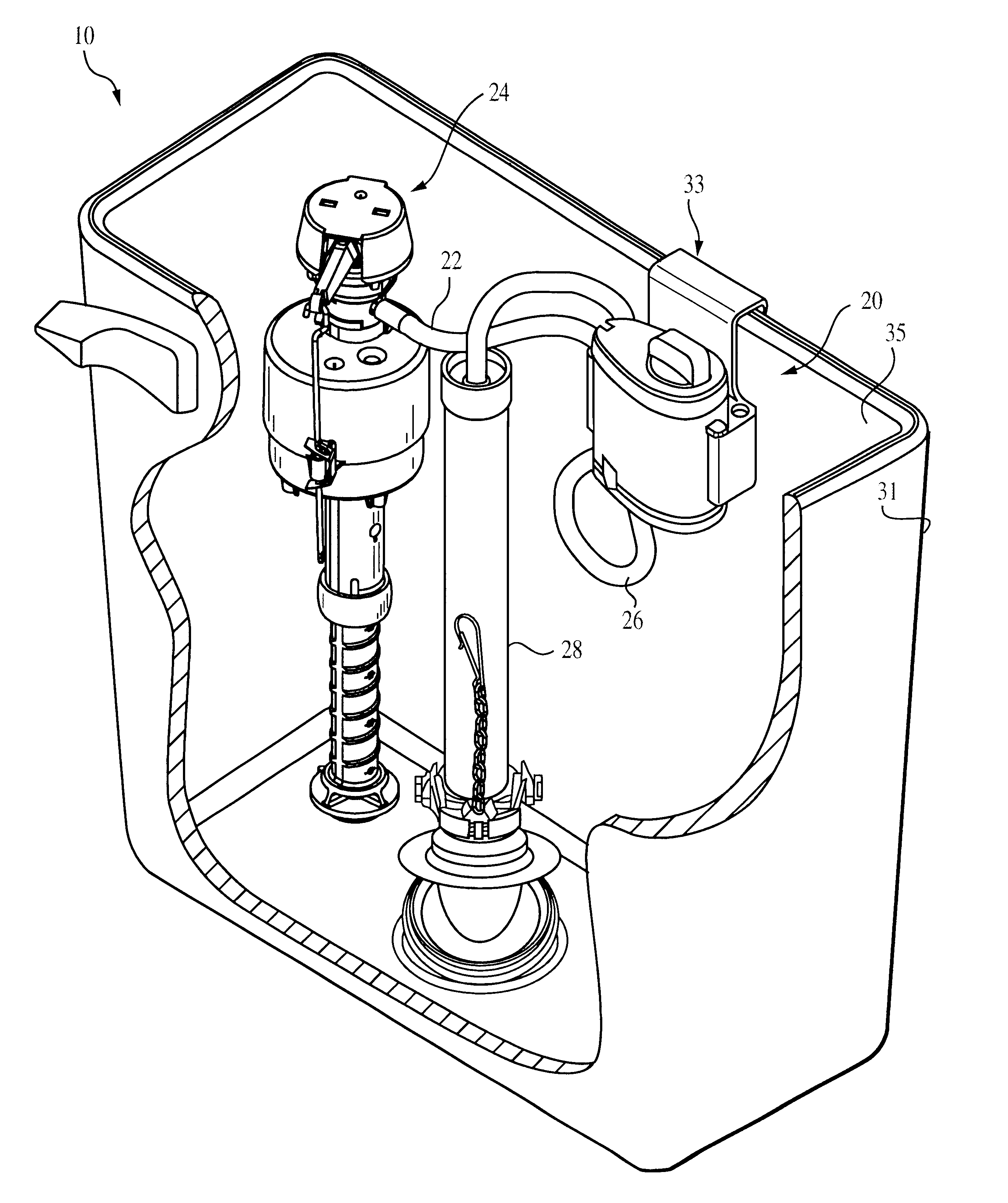
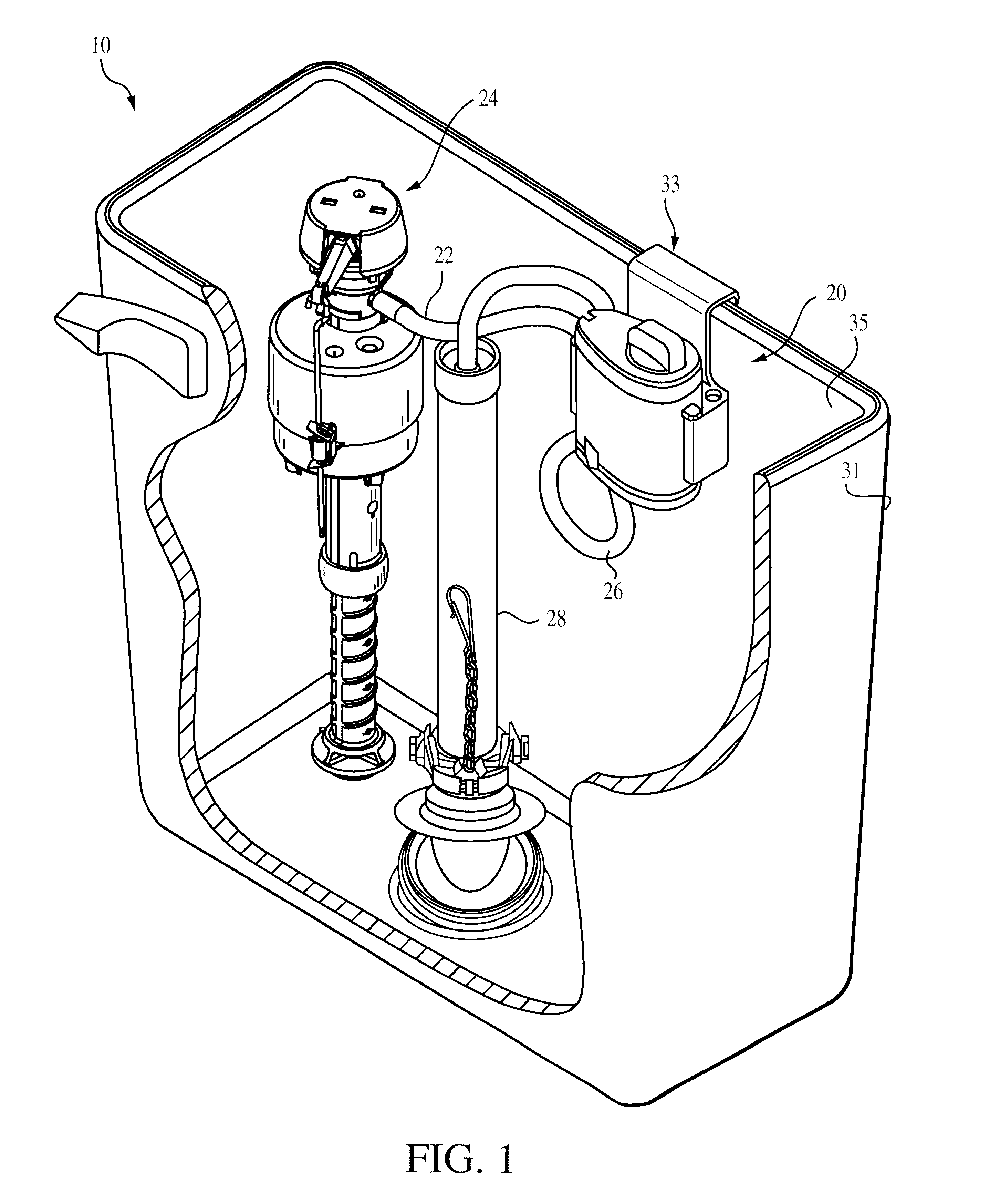
FIG. 1 is a perspective view of a toilet tank assembly 10 employing a preferred dispenser system 20 according to the invention. The dispenser assembly 20 is coupled to a fill valve 24 and an overflow tube 28. In particular, a fill tube 22 extends from the fill valve 24 to the dispenser system 20. An outflow tube 26 is coupled to the dispenser system 20 and the overflow tube 28.

The dispenser system 20 is adapted for placement within a toilet tank 31. In particular, the system 20 includes a hanger 33 configured to hang from a rear sidewall 35 of the tank 31. The system 20 is thus sufficiently compact to fit conveniently within the tank 31 while enabling easy access for maintenance.

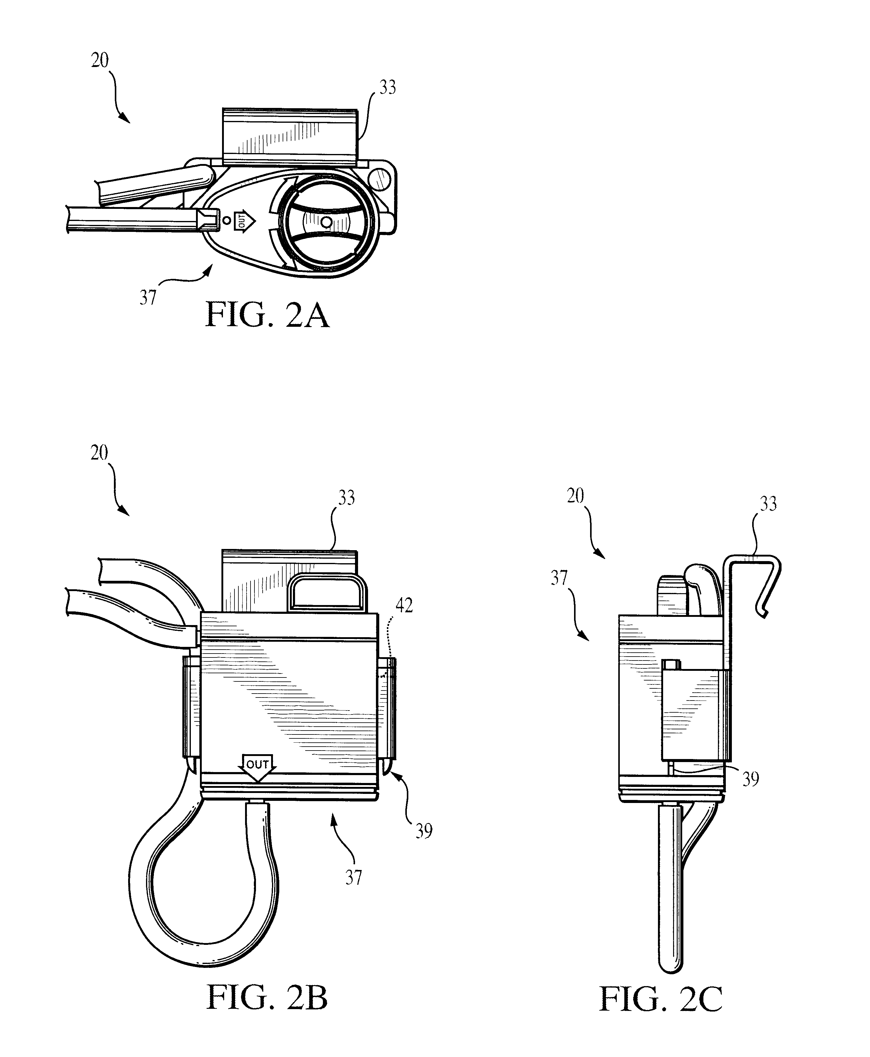
In FIGS. 2A-2C, the dispenser system 20 includes a dispenser housing 37 preferably configured to be removably coupled to the hanger 33. In a preferred embodiment, the dispenser housing 37 comprises ratcheted tabs, or detents, 39, shown also in FIG. 3, that slide into slots 42 defined in the hanger 33. It is ...


PUM


Abstract

A toilet cleaning dispenser system adapted for placement in a toilet tank includes a hanger, a dispenser housing and a cartridge device removably coupled to the dispenser housing. The cartridge device, which includes a cleanser tablet enclosed within a cartridge housing, is inserted into a cavity of the dispenser housing and turned in one direction to lock the device and, alternatively, in an opposite direction to unlock the device. The cartridge housing may be formed to turn as one unit, or be formed as a basket and a rotatable cap that can be turned with respect to the basket. The dispenser housing includes an inlet water trap and an outlet water trap, each comprising a pair of concentric, nested tubes that retain liquid after flushing so as to prevent fumes from exiting the dispenser housing into the toilet tank.

Description

1. Field of the InventionThe invention relates generally to cleaning dispensers for toilet tanks.2. Description of Prior Art and Related InformationCleaning systems for toilets typically include a cleaning agent composed of water soluble material formed into a tablet. The tablet is commonly disposed in the toilet bowl or the toilet tank. When placed in the toilet bowl, the cleaning agent is coupled to an interior of the bowl by supporting means, such as wires. Since a cleaning agent must be capable of dissolving quickly due to the short duration in which passing water makes contact with the agent, such cleaning agents get used quickly. This requires the frequent replacement of the supporting means. Since the supporting means is located in the toilet bowl, manually replacement can be messy and undesirable.Cleaning agents, such as tablets, for placement in a toilet tank are also adapted to dissolve quickly. This results in the release of fumes and various other gases which can cause d...

Claims


Application Information

Patent Timeline
Patent Type & Authority Patents(United States)
IPC IPC(8): E03D9/03E03D9/02
CPCE03D9/037E03D2009/024
Inventor NGUYEN, JACK T.MAIWANDI, FARIDLODHE, DANCOPPOCK, CHRISTOPHER A.BELL, TROY A.
Owner FLUIDMASTER
Why Eureka
Try Eureka