Air amount detector for internal combustion engine

a technology for internal combustion engines and detectors, which is applied in the direction of machines/engines, electric control, instruments, etc., can solve the problems of delayed response, unsatisfactory mass flow system, and delay in response of airflow meters

Inactive Publication Date: 2003-12-16
DENSO CORP
View PDF6 Cites 44 Cited by
  • Summary
  • Abstract
  • Description
  • Claims
  • Application Information

AI Technical Summary

Benefits of technology

According to the present invention, a response delay of an intake air flow detection means for detecting a air flow of the intake air flowing in an intake air passageway of the internal combustion engine is compensated by response delay compensation means. An intake air system model is used for modeling a behavior of an intake air which passes through a throttle valve and flows into cylinders, so that an output of the response delay compensation means is input to the intake air system model to calculate an output of the intake air system model as an air amount inside cylinder by a calculation means. In this case, because the response delay compensation means for compensating the response delay of the intake air flow detection means is provided, it is possible to calculate the air amount inside cylinder from a detection value of the intake air flow amount even during the transient period with a desirable response, thereby enabling to improve calculation accuracy of the air amount inside cylinder.

Problems solved by technology

However, during a transient period, a response of the airflow meter delays (e.g., in a case of a thermo airflow meter, a response is delayed due to the heat mass of a sensor portion of the airflow meter itself).
Thus, the massflow system has a disadvantage of an undesirable response during the transient period.
However, the air amount inside cylinder changes by depending not only on the intake air pressure, but also on volumetric efficiency and an intake air temperature, so that a calculation result of the air amount inside cylinder may have a margin of error due to an influence of a detection error or the like.

Method used


Image

  • Air amount detector for internal combustion engine
  • Air amount detector for internal combustion engine
  • Air amount detector for internal combustion engine

Examples


Embodiment Construction

An embodiment according to the present invention applied to an engine with an intake / exhaust variable valve timing mechanisms will be described.

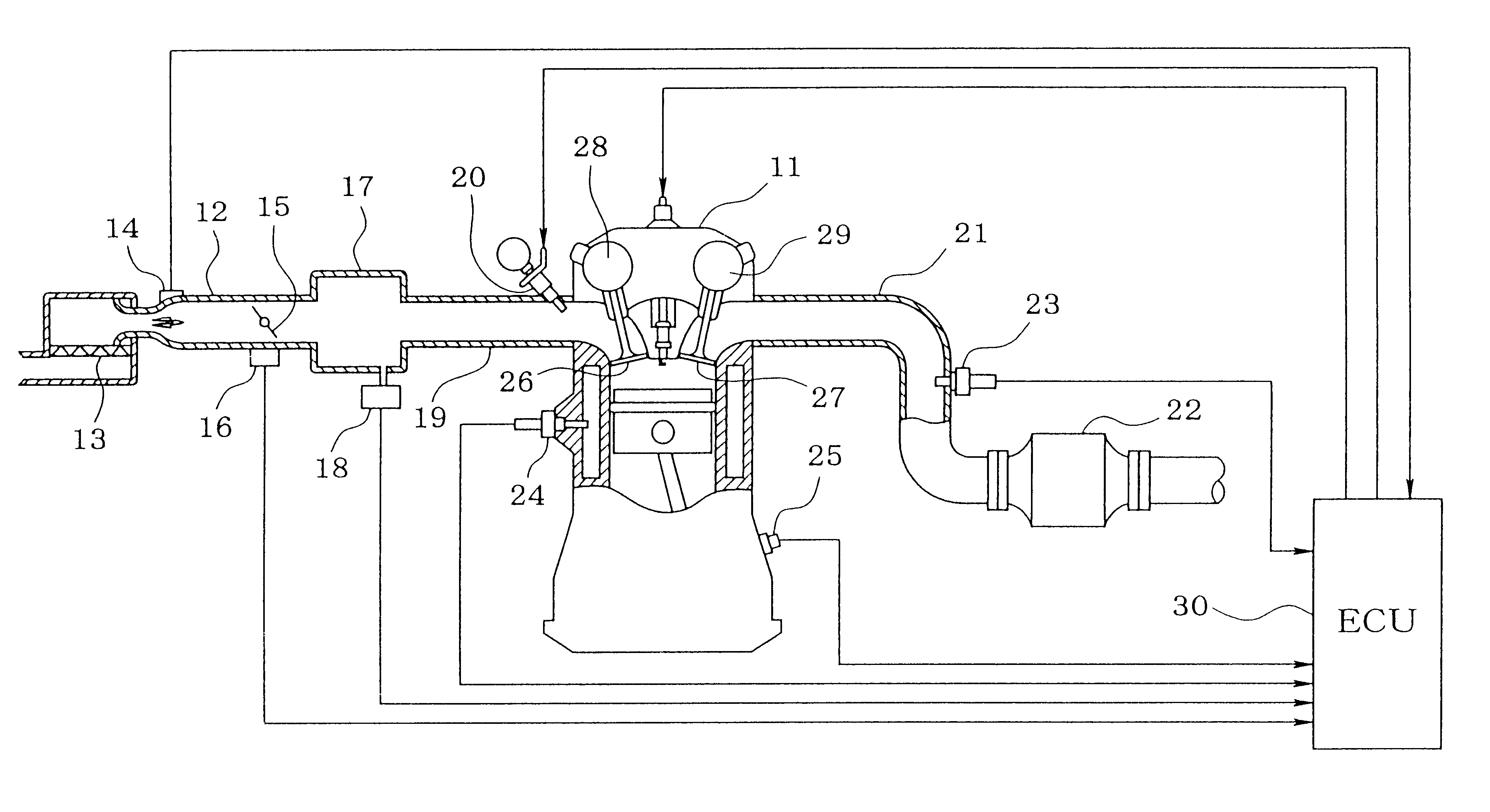
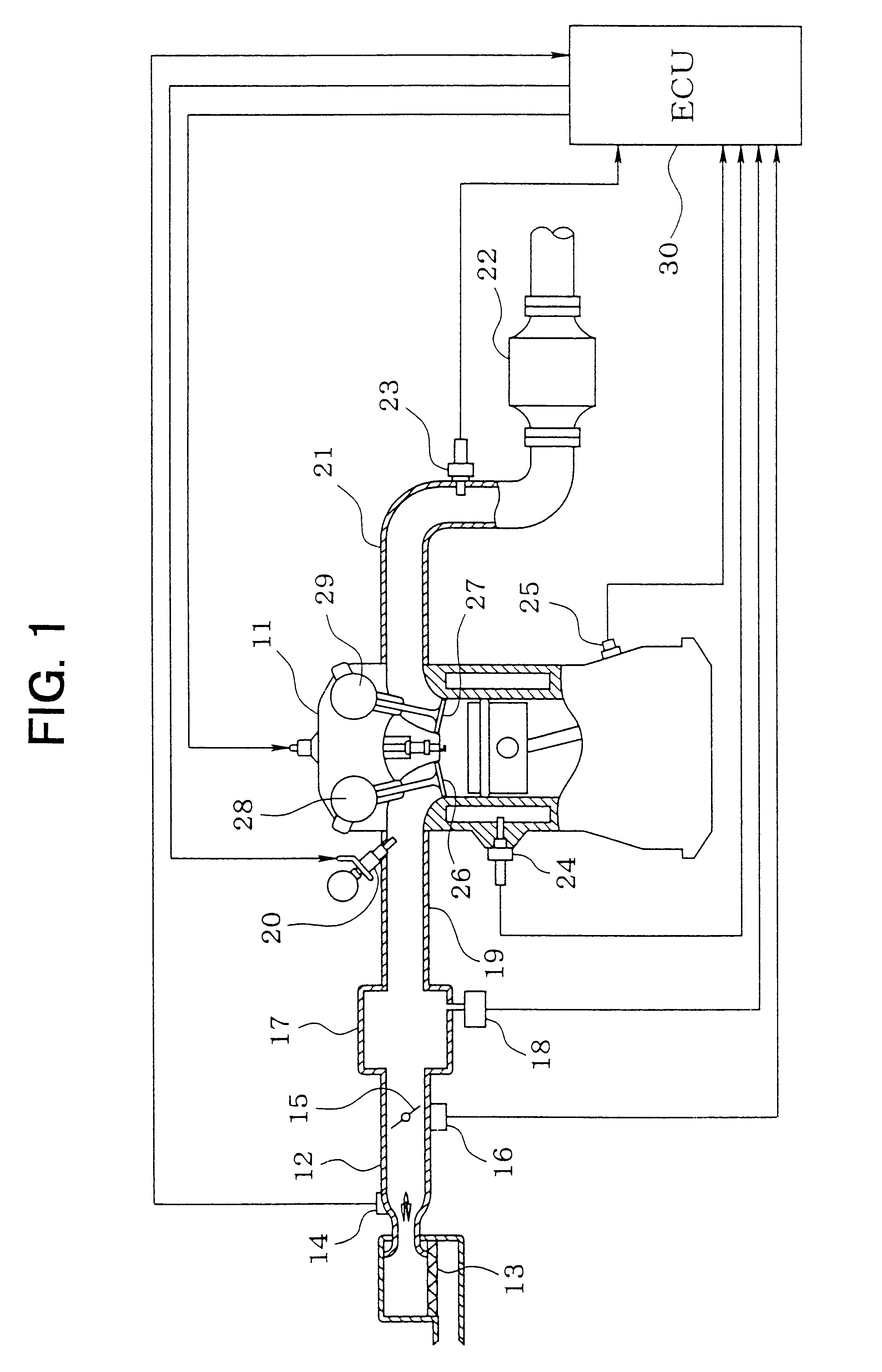
A general structure of an entire engine control system will be described with reference to FIG. 1. At a most upstream side of an intake pipe 12 (intake air passage) of an engine 11, an air cleaner 13 is provided. At a downstream side of the air cleaner 13, a thermal airflow meter 14 (an intake air flow amount detection means) for detecting an intake air flow is provided. The airflow meter 14 has a heat wire (not illustrated) disposed in the intake air flow and an intake air temperature detection element (not illustrated) housed therein, so that supply current to the heat wire is controlled so as to keep a constant temperature difference between a temperature of the heat wire cooled by the intake air and a temperature of the intake air. Accordingly, the supply current to the heat wire changes corresponding to a heat radiation amount of the he...


PUM


Abstract

A response delay compensation element for compensating a response delay of an output gMAF of an airflow meter by a phase advance compensation is provided so that an output g of the response delay compensation element is input to the intake air system model. A transfer function of the phase advance compensation iswhere T1 and T2 are time constant of the phase advance compensation, which is set based on at least one of the output gMAF of the airflow meter, engine speed, an intake air pressure, and a throttle angle. The model time constant tauIM of the intake air system model is calculated by variables including volumetric efficiency and the engine speed. The volumetric efficiency is calculated by two-dimensional map having the engine speed and the intake air pressure as parameters thereof.

Description

This application is based on and incorporates herein by reference Japanese Patent Application No. 2000-324677 filed on Oct. 19, 2000.1. Field of the InventionThe present invention relates to an air amount detector for an internal combustion engine, which detects a flow amount of intake air and calculates an air amount inside cylinder.2. Description of Related ArtIn general, methods for measuring an air amount inside cylinder of an engine are classified broadly in two schemes: One is a method in which an intake air flow is detected by an airflow meter, and then the air amount inside cylinder is calculated based on the detected value (hereinafter referred to as a mass-flow system); and the other is a method in which an intake air pressure is detected by an intake air pressure sensor, and then the air amount inside cylinder is calculated based on the intake air pressure and rotation speed of the engine (hereinafter referred to as a speed-density system). The mass flow system has an adv...

Claims


Application Information

Patent Timeline
Patent Type & Authority Patents(United States)
IPC IPC(8): F02D41/18F02D41/14F02D13/02F02D45/00F02D35/00F02D41/04
CPCF02D41/1401F02D41/182F02D13/0203F02D13/0253F02D2200/703F02D2041/1431F02D2200/0402F02D2200/0411F02D2200/0414F02D2041/001
Inventor YAGI, TOYOJI
Owner DENSO CORP
Why Eureka
Try Eureka