
Ambient field level monitor device for radio mobile terminal

a monitor device and ambient field technology, applied in the direction of transmission monitoring, frequency-division multiplex, synchronisation arrangement, etc., can solve the problems of affecting the smoothing time of the low-pass filter, and the inability to adjust the level of the monitor devi

Inactive Publication Date: 2003-12-23
FUJITSU LTD
View PDF8 Cites 7 Cited by
  • Summary
  • Abstract
  • Description
  • Claims
  • Application Information

AI Technical Summary

Problems solved by technology

Meanwhile, when the mobile station 60 makes the measurement of the RSSI value, owing to the influence of the two facts: 1 the received level variation caused by the fading and 2 the RSSI value sampling error occurring because the level detection is made in a non-synchronous (asynchronous) condition, the measurement result becomes unstable and its accuracy drops.
Further, the RSSI value sampling error originates from the fact that the amplitude of the reception signal varies at all times. With reference to FIG. 20, a description will be given hereinbelow of this error.
In this case, the time constant of its low-pass filter increases to cause the smoothing time of the low-pass filter to be prolonged, and the integration of the amplitude variation due to the shifting of the RSSI detection timing reduces the measurement error.
However, the above-mentioned publication 1 does not disclose a technique for improving the accuracy of the detection of the RSSI value.
In addition, in the case of the technique in which a capacitor with a large capacitance is incorporated into the RSSI detection circuit as mentioned above, increasing the constant of a capacitor to be incorporated into the RSSI detection circuit causes an increase in the time constant of the low-pass filter, which interferes with the RSSI measurements to be made by two antennas during the control slot LM time period to produce the drawbacks such as a diversity malfunction, an decrease in the diversity gain and a decrease in the RSSI detection value.

Method used


Image

  • Ambient field level monitor device for radio mobile terminal
  • Ambient field level monitor device for radio mobile terminal
  • Ambient field level monitor device for radio mobile terminal

Examples


first embodiment

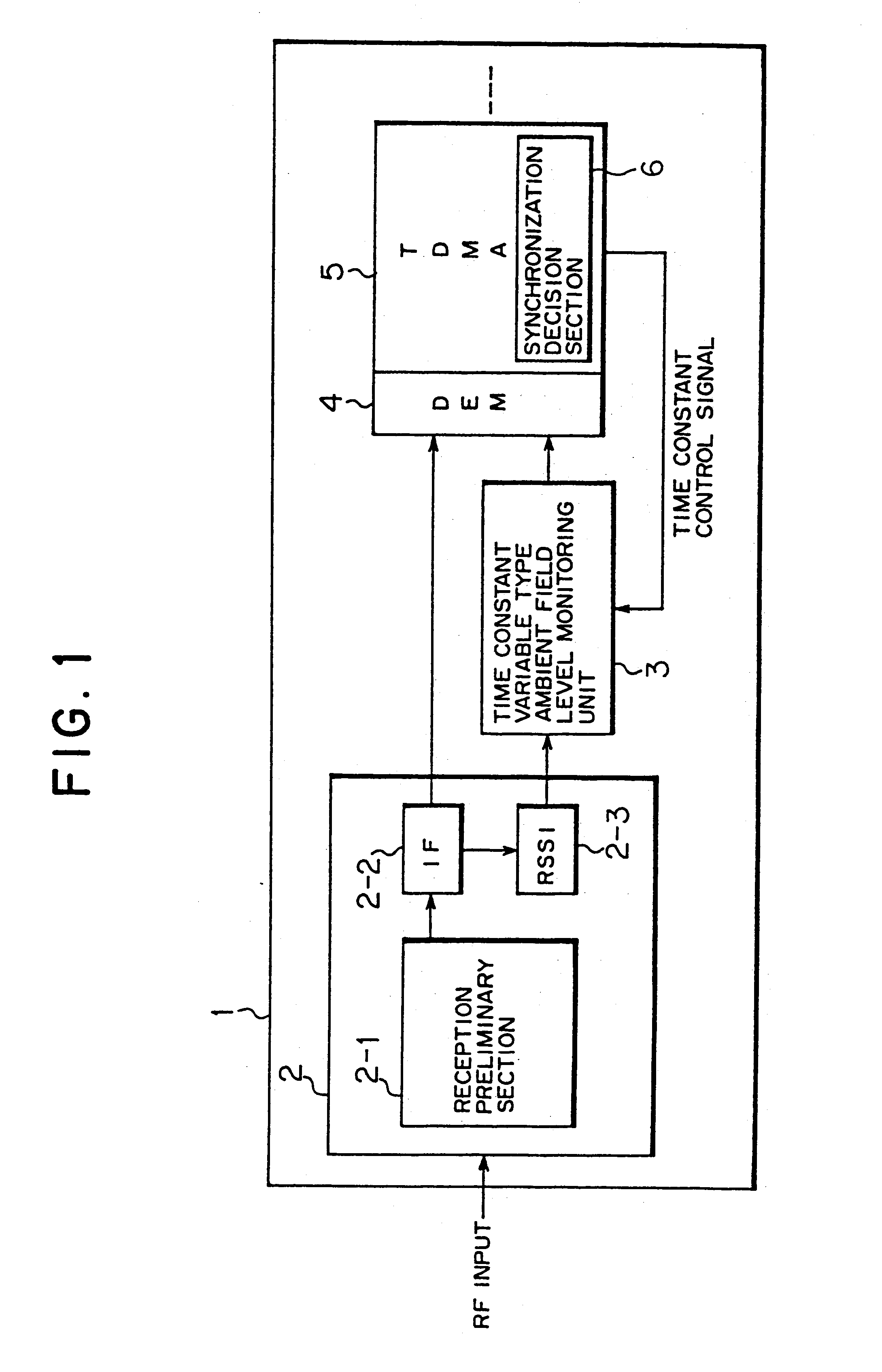
FIG. 1 is a functional block diagram showing an ambient field level monitor device according to this invention. In FIG. 1, an ambient field level monitor device, designated generally at numeral 1, is applicable to a radio mobile terminal and is made to detect the magnitude of a carrier level from a base station within a peripheral cell. The carrier level detected is transmitted as information, needed for the radio mobile terminal to shift into another cell, to a base station being currently on the communication. That is, in a Japanese PDC system, during an idle slot time period, a radio mobile terminal (mobile station) measures its received signal strength intensity (RSSI) value of the ambient cell and transmits it to a base station, while the base station performs the allocation of a channel of a mobile terminal (which will sometimes to be referred hereinafter to as a mobile equipment), on the basis of the measurement result. A description will be given hereinbelow of a radio mobil...

second embodiment

(B) Description of Second Embodiment of this Invention

It is also possible that the ambient field level monitoring unit in the above-described first embodiment and modifications thereof is practicably modified into a further different configuration.

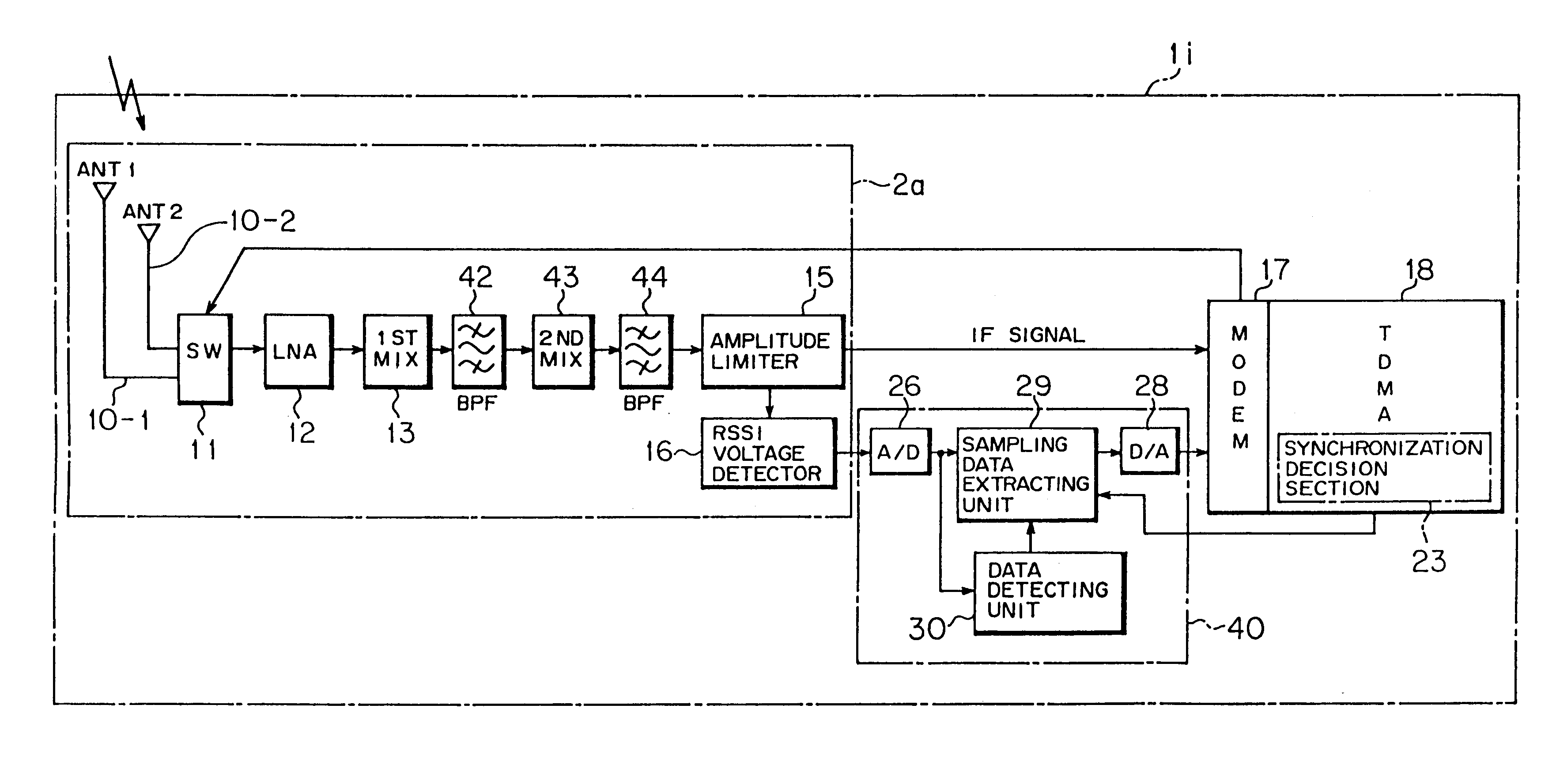
FIG. 14 is a block diagram showing an ambient field level monitor device according to a second embodiment of this invention. In FIG. 14, the ambient field level monitor device 1i is made up of a reception unit 2a, a modulator / demodulator 17, a TDMA control unit 18 and an ambient field level monitoring unit 40. This ambient field level monitoring unit 40 is not made to change a time constant unlike the above-described embodiment and modifications.

In this configuration, the reception unit 2a is for receiving a radio signal to output a reception signal originating from the received radio signal and further to output an ambient field level signal. The reception unit 2a is composed of reception antennas 10-1, 10-2, an antenna switching unit 11,...


PUM


Abstract

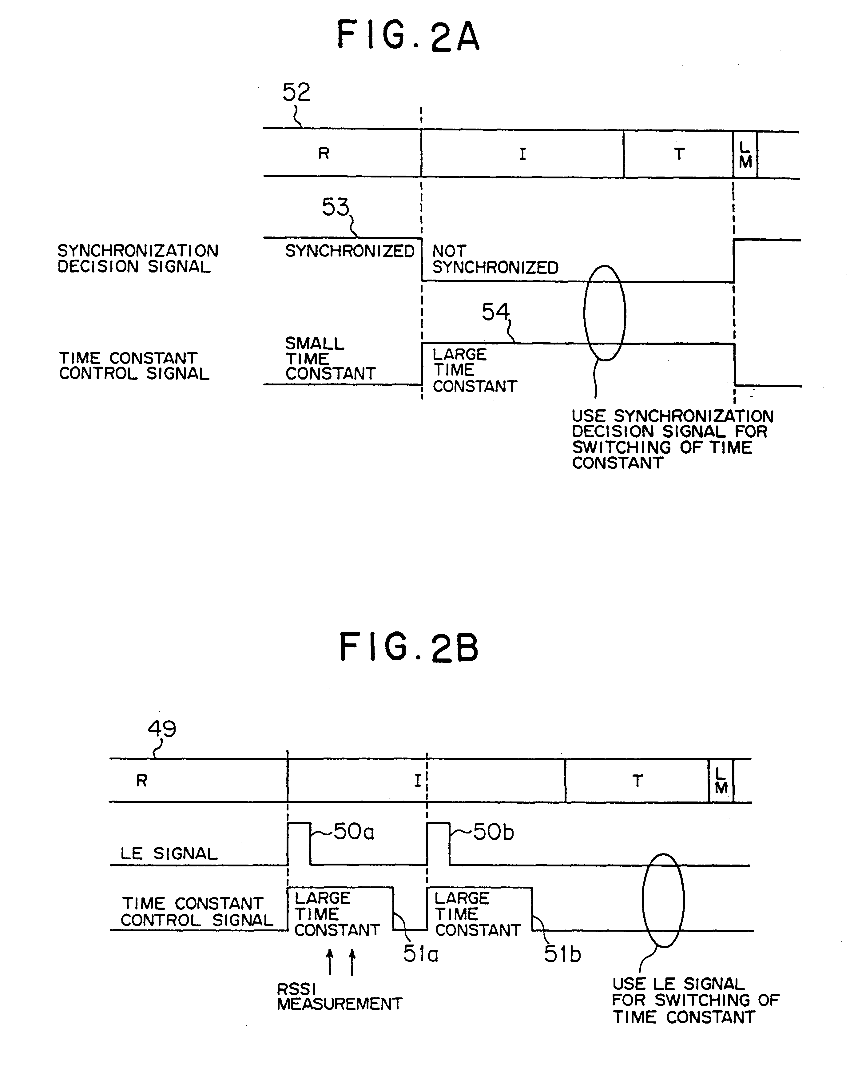
The present invention relates to an ambient field level monitor device for a radio mobile terminal, comprising a reception unit for receiving a radio signal arriving at the radio mobile terminal to output a reception signal originating from the received radio signal and further to output an ambient field level signal, a synchronization decision section for receiving the reception signal from the reception unit to judge whether or not the reception unit is in synchronism with the received radio signal, and a time constant variable type ambient field level monitoring unit for receiving the ambient field level signal from the reception unit. If the synchronization decision section judges that the reception unit is out of synchronism with the received radio signal, the ambient field level monitoring unit increases its time constant so that the time constant exceeds its time constant to be taken for when the synchronization decision section judges that the reception unit is in synchronism with the received radio signal and if the synchronization decision section judges that the reception unit is synchronism with the radio signal, the ambient field level monitoring unit decreases the time constant. This reduces the measurement error caused by the difference between sampling timings, thereby enabling stable RSSI value detection irrespective of a phase synchronization condition of a mobile station to improve the detection accuracy.

Description

1) Field of the InventionThe present invention relates to an ambient field level monitor device applicable suitably for a radio mobile terminal or station.2) Description of the Related ArtIn the recent years, with an explosive increase of portable telephone subscribers, communication enterprises installs a large number of base stations and increase the number of channels to be put to use, thereby attempting to stabilize communications.Viewing a channel detection method taken in a Japanese PDC (Personal Digital Cellular) system, a radio mobile terminal, forming a mobile station, detects the level of a carrier from a base station within a peripheral cell during an idle slot time to measure a value of its received signal strength intensity (which will be referred hereinafter to as an RSSI), and reports the measurements to the base station, while the base station receives that report successively. During communications with the mobile station, if a peripheral cell exists which shows a r...

Claims


Application Information

Patent Timeline
Patent Type & Authority Patents(United States)
IPC IPC(8): H04B17/00H03G9/00H03G11/06H04B7/26H04W24/00H04W48/16H04W56/00
CPCH04B17/318
Inventor MITSUME, HIROYUKITAKAHASHI, HIROKI
Owner FUJITSU LTD
Learn More