Apparatus and method for wireless gas monitoring

a wireless gas monitoring and apparatus technology, applied in the direction of electric signalling details, fire alarms, instruments, etc., can solve the problems of requiring substantial and frequent maintenance, laborious and expensive rerouting of all cables, and difficulty in locating multiple wires in the ground, and achieves the effect of reducing the number of wires

Inactive Publication Date: 2003-12-30
GASTRONICS
View PDF16 Cites 90 Cited by
  • Summary
  • Abstract
  • Description
  • Claims
  • Application Information

AI Technical Summary

Problems solved by technology

Hard wiring each of the numerous monitors to the control system can be quite costly, cumbersome and require substantial and frequent maintenance.
Rerouting all of the cables is labor intensive and expensive.
Burying multiple wires in the ground requires substantial excavation which is rarely inexpensive.
Similarly, repairing, replacing or moving these wires also requires substantial, expensive excavation.
This, again, may be an expensive undertaking.
Finally, with regard to hard wiring, the wires themselves are usually expensive and are prone to breaking, cracking or failing in some sort of way.
Consequently, the monitors may have to transmit information a substantial distance.
In addition to physical barriers, the monitors usually need to transmit the information through substantial interference as well.
Electric equipment and communication systems existing in almost all plants create vast amounts of interference such as electromagnetic waves, for example.
A typical radio telemetry system using RTU's, while reducing significant installation costs, still requires both the high cost of the RTU as well as the installation costs to wire the gas monitors to the RTU.
This particularly true with respect to very long conduit runs, such as with perimeter monitoring applications, where the cost of the RTU and wiring the sensors to the RTU is increased by the long lengths of the conduit and installation costs.
However, the actual concentration, i.e. the dangerously high 20 ppm of gas alpha, would not be relayed back to the control room.
This type of system would not provide and quantitative documentation which may be useful in any number of situations.

Method used


Image

  • Apparatus and method for wireless gas monitoring
  • Apparatus and method for wireless gas monitoring
  • Apparatus and method for wireless gas monitoring

Examples


Embodiment Construction

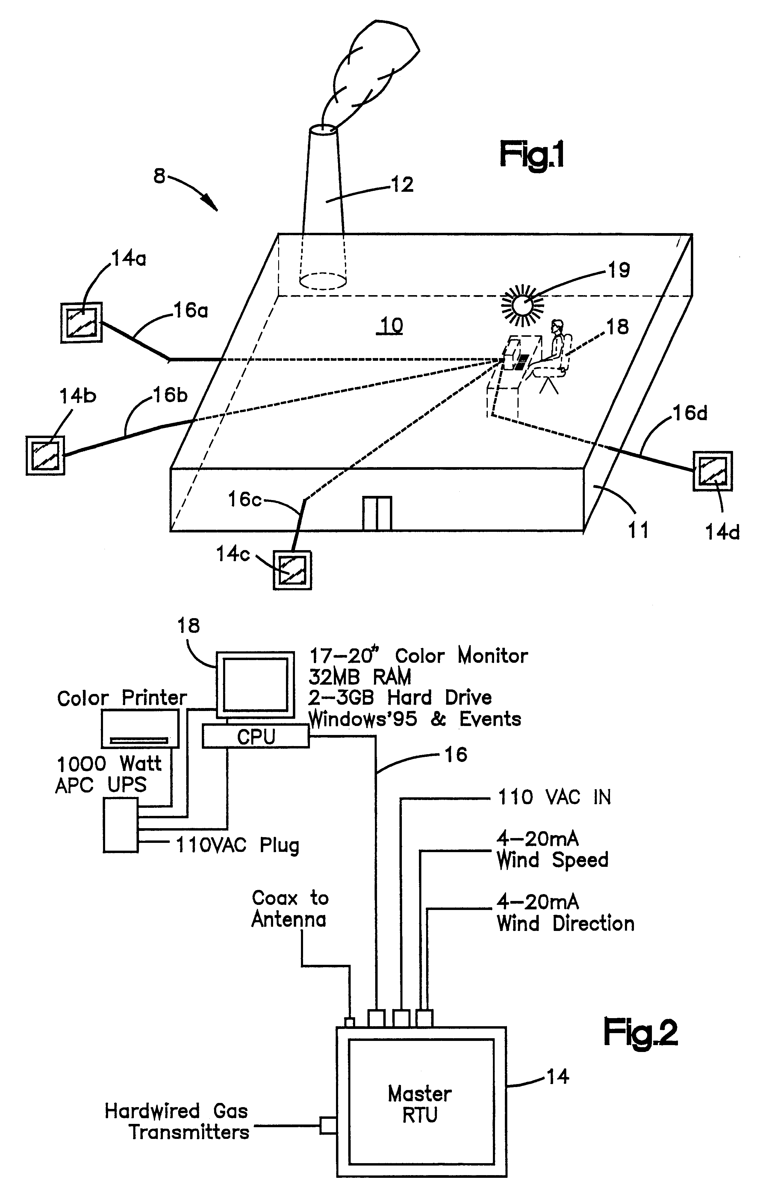
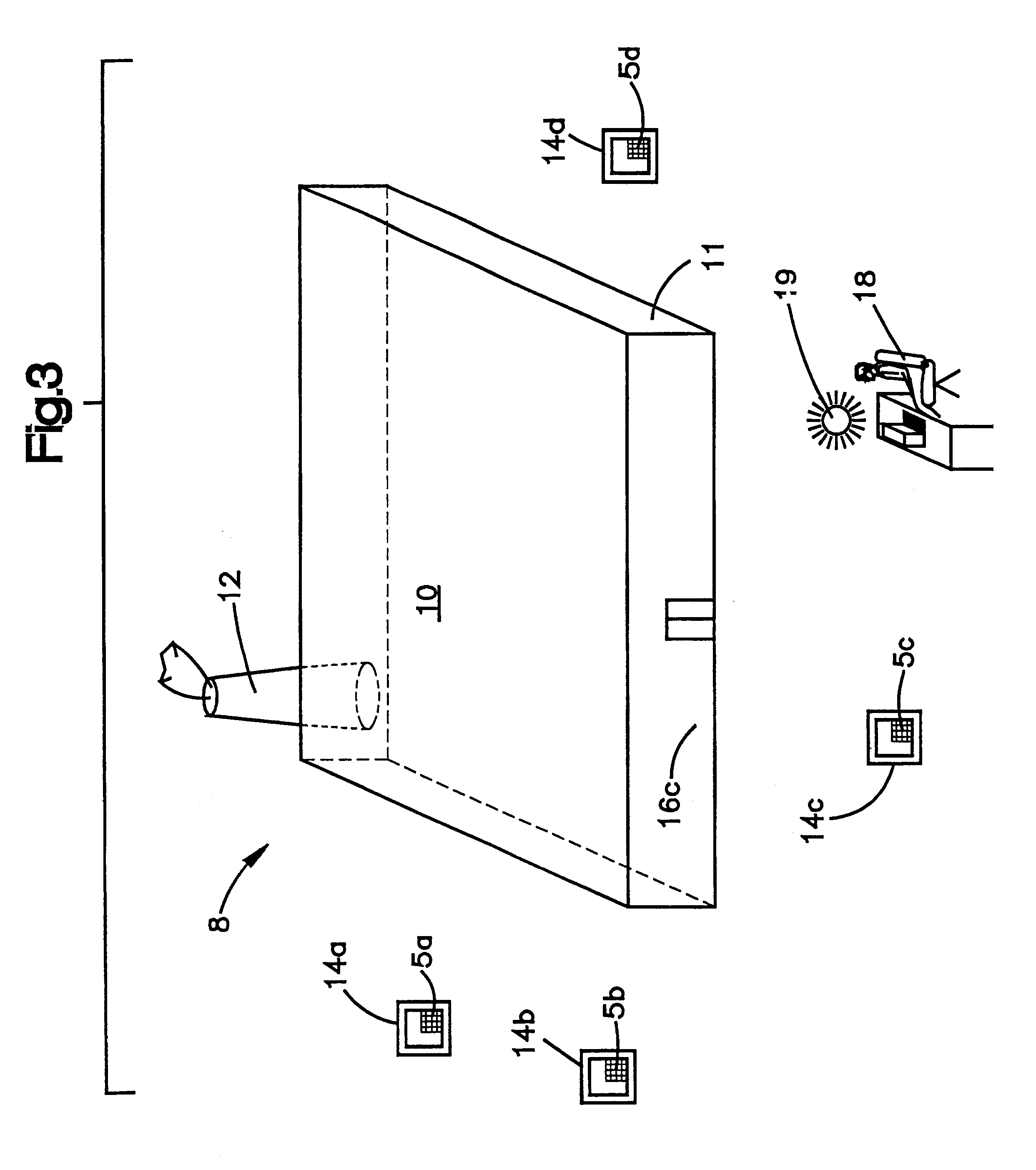
Referring now to the drawings, which are for purposes of illustrating a preferred embodiment of the invention only, and not for purposes of limiting the invention, FIG. 1 shows a chemical processing plant 10. The plant 10 is depicted as having a discharge means 12. The discharge means 12 are a potential source of a selected gas. Multiple toxic gas monitors or monitor stations 14a, 14b, 14c 14d are placed around the plant 10. FIGS. 1 and 2 show the previous technology wherein each monitor or station 14a, 14b, 14c, 14d had to be hard wired via cables 16a, 16b, 16c, 16d to the control center or master station 18. Should control center or master station 18 need to be relocated at a different site, such as outside of the plant 10, the cables 16a, 16b, 16c, 16d would need to be extended to this remote site. Such a configuration and any changes to such a configuration were expensive, labor intensive and required substantial frequent maintenance.

FIG. 2 depicts the interconnection of some of...


PUM

PropertyMeasurementUnit
timeaaaaaaaaaa
voltageaaaaaaaaaa
battery voltageaaaaaaaaaa

Abstract

The current invention provides a wireless monitoring system. The system has one or more monitoring devices. Each device can transmit data and receive messages from an output center or alarm system. The output center can also transmit and receive messages. Both the output center and each device preferably have a transceiver that enables both the transmission and receipt of messages. No remote terminal units hardwiring is required for the system to function. The system is truly a wireless gas monitoring system. The system may use low earth orbit satellite technology, or licensed radio frequencies or any other means to wirelessly transmit and receive messages.

Description

This invention relates to the field of gas monitoring.The invention provides a method and apparatus for wireless monitoring of gases, including toxic and combustible gases, with a device that has a radio transmitter that transmits quantitative gas levels to a master controller or multiple master controllers.DESCRIPTION OF THE RELATED ARTToxic gas monitoring systems are well known. Generally, gas monitors are placed around chemical producing facilities such as a chemical processing plant. These monitoring systems are configured to monitor for the presence of toxic and / or combustible gases. In addition to monitoring for the presence of these gases, typically in parts per million or lower explosive limits, these detectors could be configured to detect other important information such as wind speed and direction, temperature and other weather conditions. This information is then relayed to some sort of central reporting system. For instance, the information can be relayed back to the co...

Claims


Application Information

Patent Timeline
Patent Type & Authority Patents(United States)
IPC IPC(8): G01N33/00G08B21/00G08B21/14G08B21/16
CPCG01N33/0075G08B21/16G08B21/14
Inventor DUNGAN, CORNELIUS P.
Owner GASTRONICS
Why Eureka
Try Eureka