Multi-diaphragm valve

a multi-diaphragm, valve technology, applied in the direction of diaphragm valves, engine diaphragms, couplings, etc., can solve the problems of high frictional losses through the valve, limited capacity of the diaphragm sleeve valve as the valve is shut, and the diaphragm sleeve valve requires less maintenan

Inactive Publication Date: 2004-01-06
GILL AJIT SINGH
View PDF2 Cites 8 Cited by
  • Summary
  • Abstract
  • Description
  • Claims
  • Application Information

AI Technical Summary

Benefits of technology

This invention provides a bell type diaphragm which simultaneously puts the diaphragm in stretch and compression mode, which mitigates the effect of the harmful stretch. It also divides the diaphragm into two sections, where the first section acts as a check valve and the second section acts as a regular valve. Thus, two valves (in the same valve) are provided with one diaphragm. Since each of the said two sections of a diaphragm requires half of the fluid volume usually required by conventional sleeve valves, both sections can be operated with twice the opening and closing speed of conventional sleeve valves. To meet some requirements, the invention provides a faster shut off valve / control valve / check valve combination.
There is demand in the industry for high capacity automatic control valves with less maintenance. Elastomeric diaphragm sleeve valves require less maintenance but their capacity as shut of valves is limited, and frictional losses through the valves are high. In one embodiment, the present valve reduces frictional losses by installing at least two concentric diaphragms in the same valve, where inlet fluid is divided between two or more diaphragms. The fluid is controlled by said diaphragms, and these diaphragms may be controlled by a single pilot valve. By using two diaphragms, the capacity of the valve is increased and frictional losses are reduced by reducing the over-all velocity of the fluid through the valve. The valve may be designed such that each of the concentric diaphragms in the valve will require different initial opening pressures. Thus, when one diaphragm is open, the other diaphragm will remain in closed position until its opening pressure is reached. Thus, the scope of the valve is enhanced, since the valve can be made to operate to handle different scenarios.
Like butterfly and ball valves, the two or more diaphragms in the same valve handle much higher fluid volume than conventional sleeve valves. Also, the double diaphragm design cuts the length and stroke of each diaphragm. This reduction in diaphragm length cuts the overall length and weight of the valve, compared to conventional sleeves valves of equal fluid capacity.
Seals and gaskets are provided against unwanted leakage inside the valve, and from the valve to the outside environment.

Problems solved by technology

Elastomeric diaphragm sleeve valves require less maintenance but their capacity as shut of valves is limited, and frictional losses through the valves are high.
The travel of the parts along the pipe is limited by the distance the pipe ends can slide into the interior chambers.

Method used


Image

  • Multi-diaphragm valve
  • Multi-diaphragm valve
  • Multi-diaphragm valve

Examples


Embodiment Construction

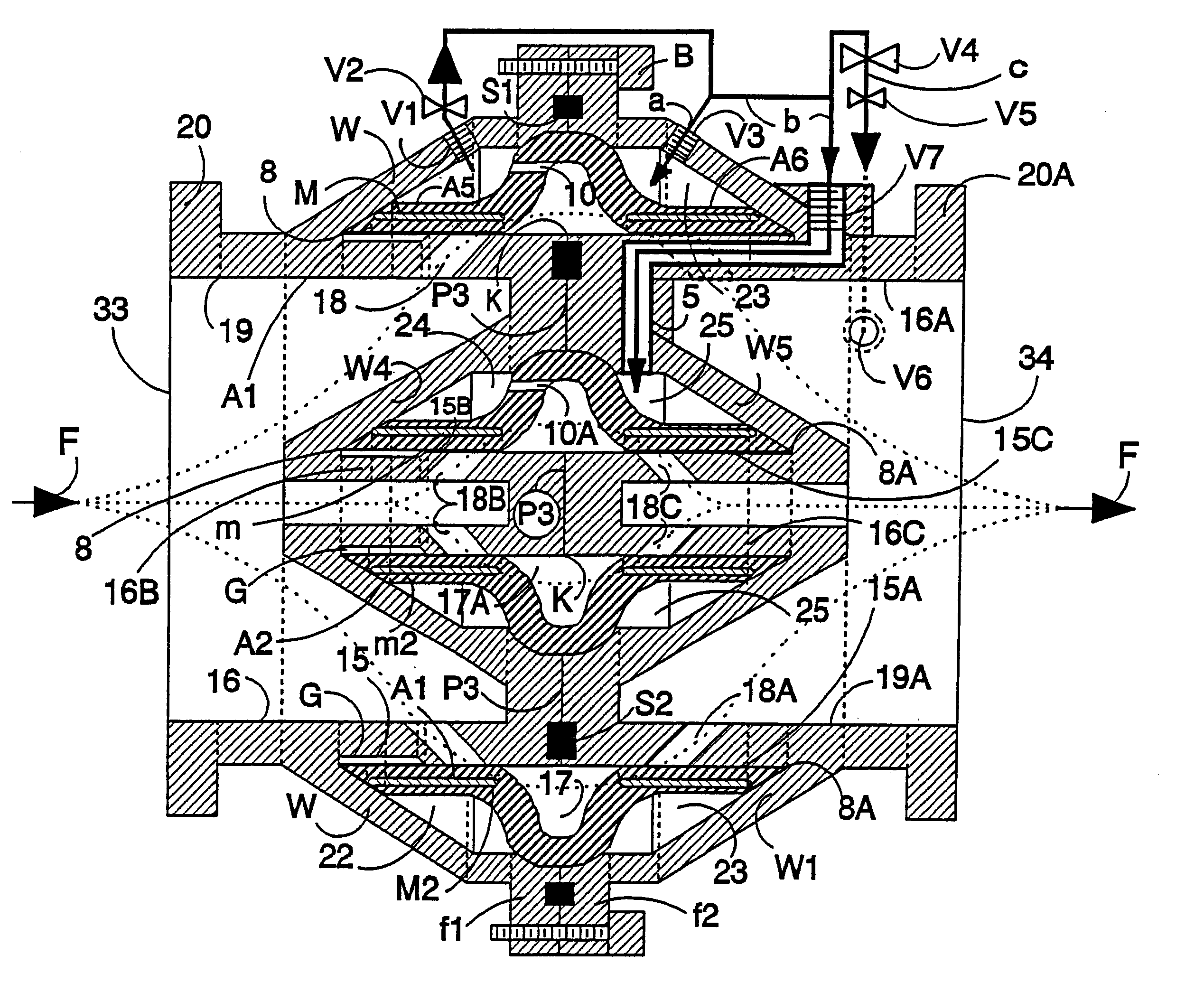
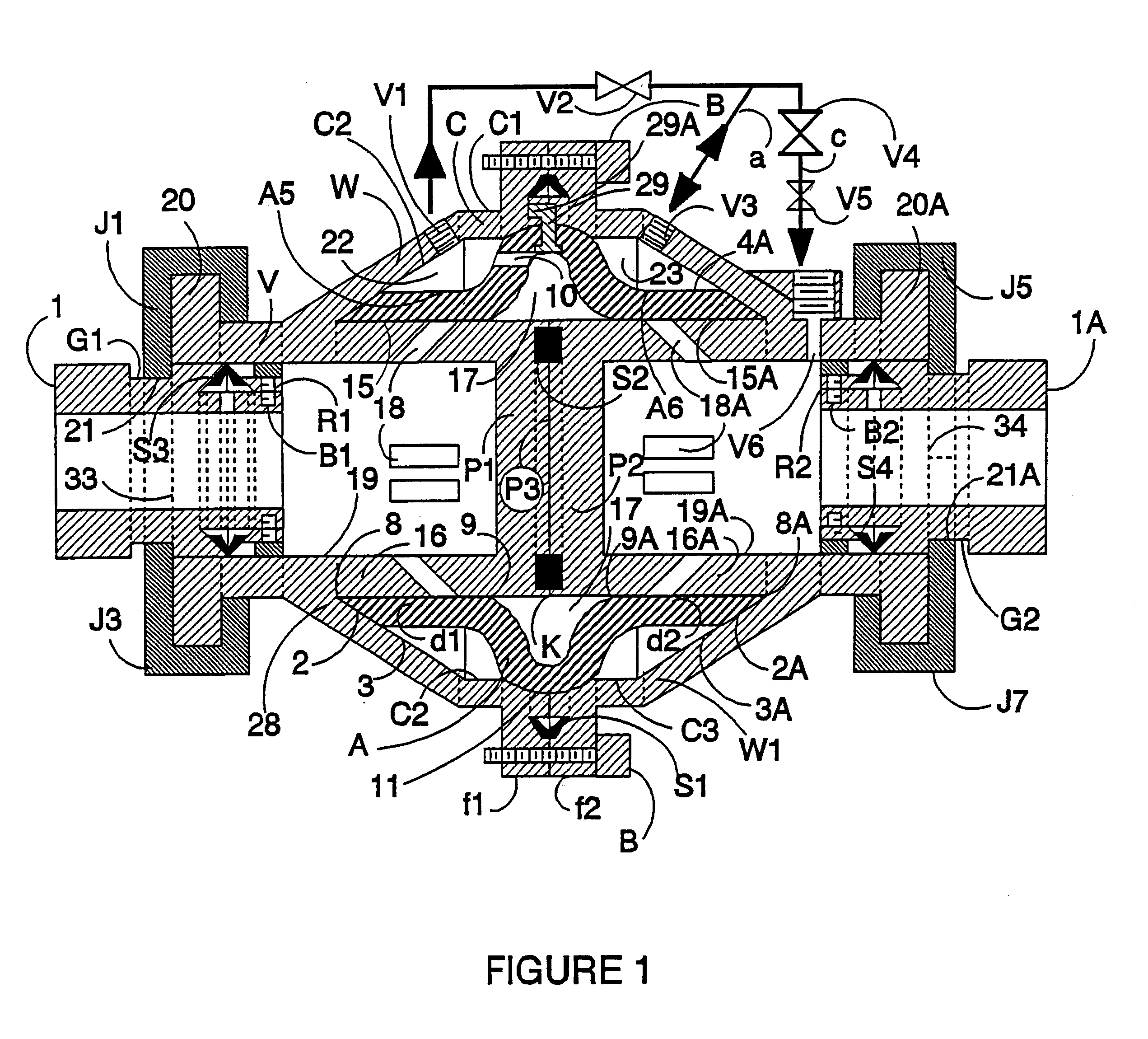
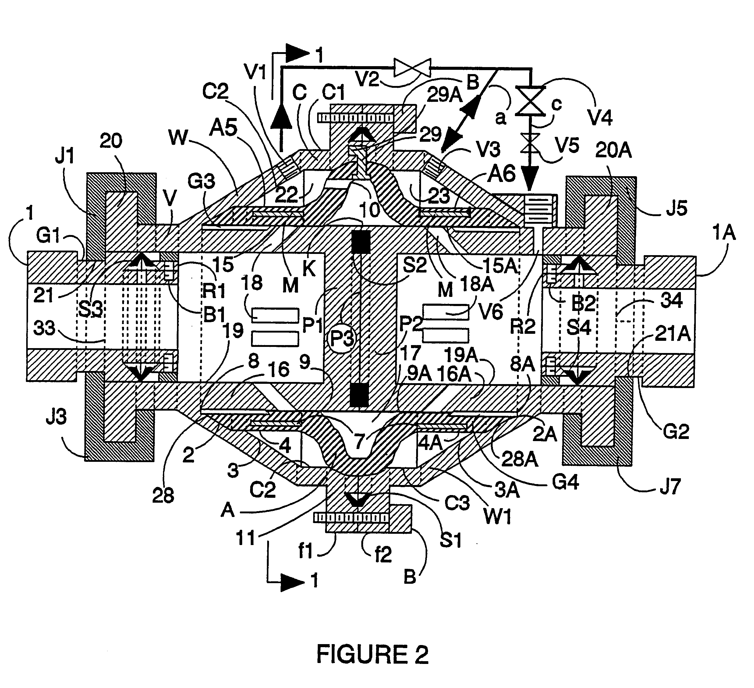
The drawings described are not to any particular scale. The valve body is constructed symmetric and concentric to the axis of the valve. Therefore, except in FIG. 3, only axial vertical sections of the valve are shown. To understand the invention, all figures can be studied together. First, FIGS. 1, 2, and 3 will be studied together. FIGS. 1 and 2 are exactly the same, except that the elastomeric diaphragm in FIG. 2 is provided with arcuate platens M, M1, M2, and M3, which are depicted in FIG. 3. If platens are used, there will always be at least one platen, but the total number of platens used can vary from valve to valve, and they can be more than four arcuate platens as depicted by the FIGS. The valve body V includes a composite body made of two parts, where each part is depicted by its outer wall W and W1 respectively. The first part has an inlet cylindrical chamber 16 with inner diameter 19. The inlet chamber 16 has cylindrical inlet 33 for the entrance of the fluid from pipe l...


PUM


Abstract

A multi-diaphragm flow control valve includes a valve body separable into two parts. Each part includes an interior chamber having a closed end which separates the chambers when the parts are joined and an open end for connection to a pipe. An outer chamber surrounds a portion of the interior chamber and is separated therefrom by an interior wall. Slots connect the interior and outer chambers. The outer chambers connect to form a diaphgram chamber when the parts are joined. A cylindrical bell type elastomeric diaphragm having a central outwardly extending hump and with legs extending axially from opposite sides of the hump is positioned in the diaphragm chamber with the respective legs of the diaphragm over the slots through the interior walls of respective parts. The diaphragm is pressurized to block or allow flow through respective slots and each leg of the diaphragm acts as an independent diaphragm.

Description

BACKGROUND OF INVENTION1. FieldThe invention is in the field of fluid control valves, pressure reducing valves, and pressure relief valves for pipe lines, all operating by means of elastomeric sleeve diaphragms.2. State of the ArtThere are diaphragm sleeve valves currently used to control fluid flow in pipe lines. These valves require the tying or securing of the ends of their sleeve diaphragms. Current sleeve valve designs require the valves to be taken out of the line when replacing their sleeve diaphragms. These valves are designed with slots of very small size, and therefore, can pass only small sized particles in the fluid. The inventor is not aware of any valve using a bell type diaphragm.The present invention provides a valve which can accommodate larger sizes of debris, and can also accommodate more than one diaphragm in the same valve, which increases the capacity of the valve. Preferably, the ends of the diaphragms are kept free, to keep them from stretching, thus increasi...

Claims


Application Information

Patent Timeline
Patent Type & Authority Patents(United States)
IPC IPC(8): F16K7/00F16K7/07F16K31/12F16L37/00F17D3/00
CPCF16K7/075Y10T137/87426Y10T137/87499
Inventor GILL, AJIT SINGH
Owner GILL AJIT SINGH
Why Eureka
Try Eureka