Ratiometric background correction for fluorescence polarization assays

a fluorescence polarization and background correction technology, applied in the field of fluorescence polarization measurement correction, can solve the problems of well-to-well variation, affecting the accuracy of fp measurement, and the degree of photobleaching

Inactive Publication Date: 2004-01-06
CAMBRIDGE RES & INSTR
View PDF4 Cites 28 Cited by
  • Summary
  • Abstract
  • Description
  • Claims
  • Application Information

AI Technical Summary

Benefits of technology

Another object of the present invention is to provide a more precise method of correcting FP measurements for the effects of background fluorescence, where the background fluorescence correction does not inject the noise or uncertainty of the conventional method into the FP measurement.
Yet another object of the present invention is to provide a correction method which does not introduce a significant source of error when fluorophore concentrations get low (e.g., below a few hundred pM).
Yet another object of the present invention is to provide a method which confers greater precision and accuracy on FP measurements than conventional methods when fluorophore concentrations get low (e.g., below a few hundred pM).
Still another object of the present invention is to provide more accurate fluorescence polarization measurements without necessarily degrading the instrument signal-to-noise ratio.
These and other objects are achieved by the present invention in which a multiplicative ratio approach is used to remove the effects of the unwanted background fluorescence rather than the conventional subtractive approach, thus preserving both the precision and accuracy of the FP measurements. The method according to the present invention, comprises selecting an appropriate multiplicative ratio is selected, then the selected multiplicative ratio is calculated using measurements from samples. The calculated multiplicative ratio is multiplied by an appropriate value in one of the standard FP measurement equations (Equations 1 or 4) or an appropriate value in an equation derived from one of the standard FP measurement equations. After (or during) this calculation, the corrected FP measurement is calculated. When such multiplicative ratios are applied to the appropriate value or values in an FP measurement equation, the effects of background noise can be reduced without decreasing the precision of the FP measurements.
In a first presently preferred embodiment of the present invention, a multiplicative ratio comprised of the relative proportion of light from a background well fluorescence emission to light from a sample well fluorescence emission is calculated, and is appropriately multiplied into the fluorescence polarization calculation, resulting in a corrected FP measurement that is both accurate and precise. In a second presently preferred embodiment, a multiplicative ratio comprised of the total intensity of the first sample divided by the total intensity of the current sample is calculated, and is appropriately multiplied by the first measured background intensity, resulting in a corrected background intensity, which is used in a corrected FP measurement equation that is both accurate and precise.

Problems solved by technology

This can affect the accuracy of the FP measurements.
The disadvantage of this approach is that the accuracy of background correction is subject to changes in excitation lamp intensity, well-to-well variations in sampled volume and meniscus, and the degree of photobleaching between the background measurement and the sample measurement.
In effect, the background correction step injects into the calculation additional noise, which reduces measurement precision.
But, as is discussed above, this is not desirable, since the precision of these measurements relative to each other is more important than the accuracy of the individual measurements.
However, this solution (of not performing any background correction) is also not desirable because of the effects of such a loss of accuracy when making comparisons between different experiments, assays, samples, etc.
For example, part of the job of assay development technicians is to compare assays from different experiments; but this is made more difficult (and the results are more questionable) when the accuracy of the measurements from the different experiments is problematic.
A particularly problematic situation is when the background signal is a substantial portion of the total signal, say 25% or more.
This limitation may be the most significant barrier to performing assays with tracer concentrations less than 100 pM.
When dealing with such small amounts, not using any background compensation is also unsatisfactory, because the effect of the background noise becomes so large in comparison to the real (probe) signal that both the precision and accuracy of the FP measurements are substantially degraded.
This is a crucial problem because many assays should be operated at such low levels, near the K.sub.d point.
This need is particularly acute when fluorophore concentrations get low (e.g., below a few hundred pM), which causes significant error in both the precision and accuracy of FP measurements in the conventional method.

Method used


Image

  • Ratiometric background correction for fluorescence polarization assays
  • Ratiometric background correction for fluorescence polarization assays
  • Ratiometric background correction for fluorescence polarization assays

Examples


first embodiment

Experimental Verification of the First Embodiment

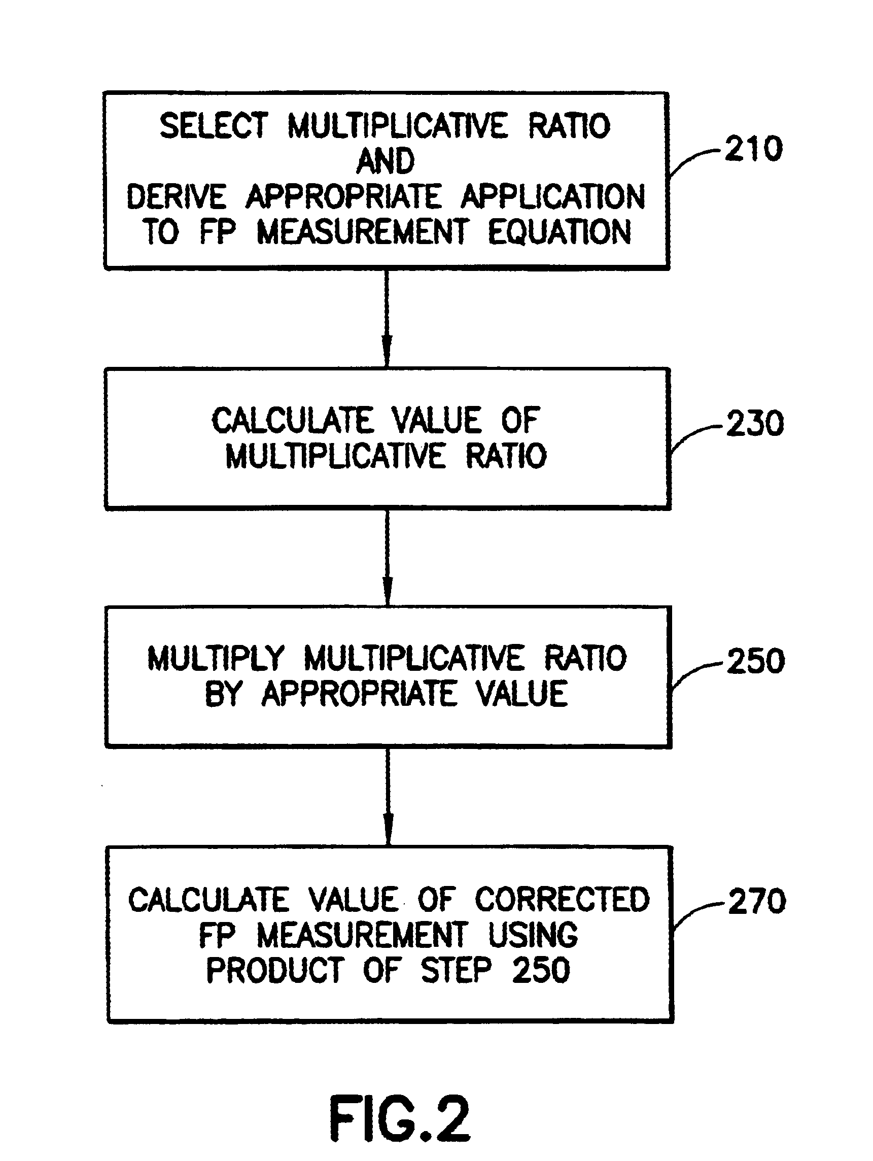
The equation derived in the first embodiment (Equation 10) was tested by making corrected FP measurements using the method shown in the flowchart of FIG. 5. For the FP measurements, several assays with known molecular interactions were used, but at label (fluorophore) concentrations well below what is used with conventional instruments. The assay material was from a pharmacogenomics single nucleotide polymorphism (SNP) experiment designed to give a high FP value when the target SNP allele is present to match the template, in this case a T allele.

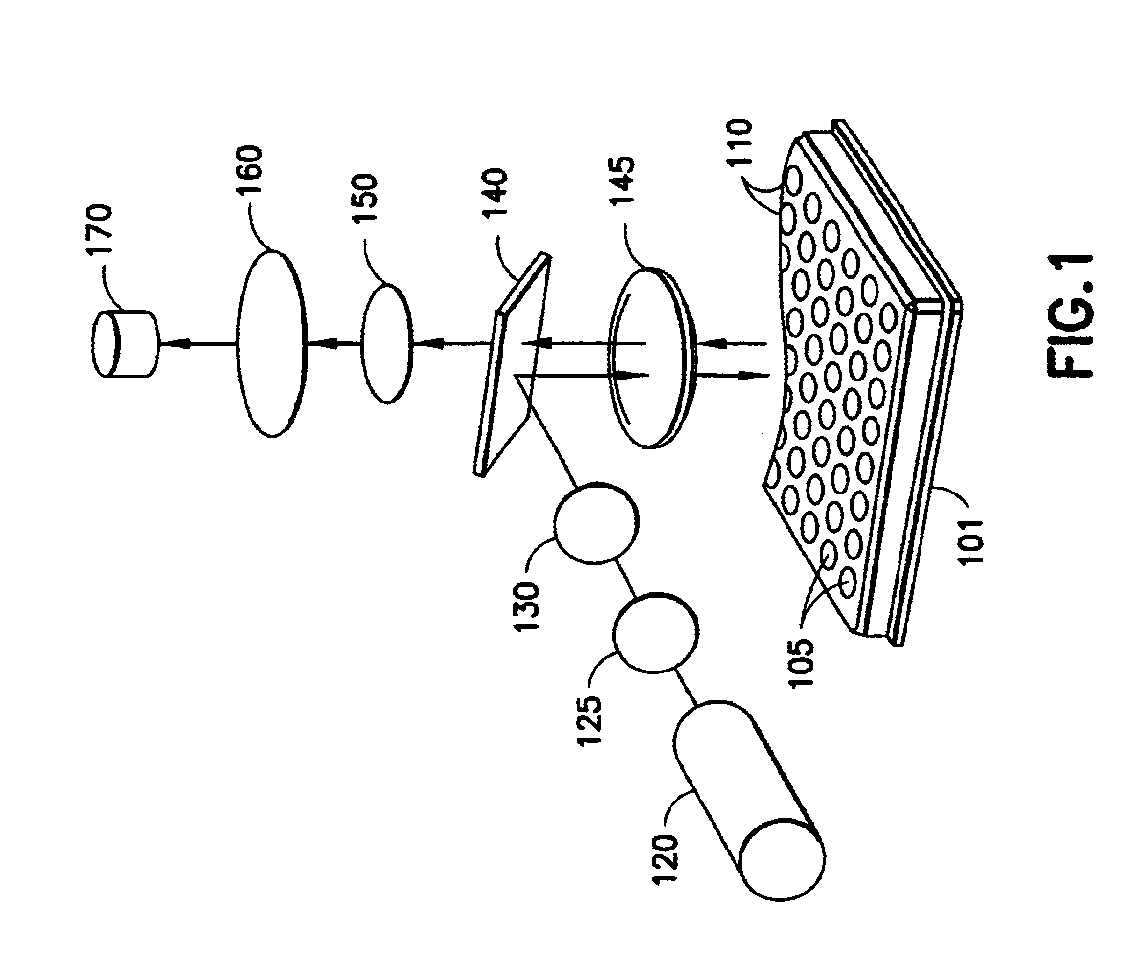
On a Symmetry FP Plate Reader prototype (this type of FP Plate Reader is now called Affinity) from Cambridge Research & Instrumentation (Cambridge, Mass.), a row of control wells were measured simultaneously by the Symmetry (Affinity) CCD camera. The left half of the row was filled with all assay materials except the fluorescence label, and the right half was filled with the typical assay mix,...

second embodiment

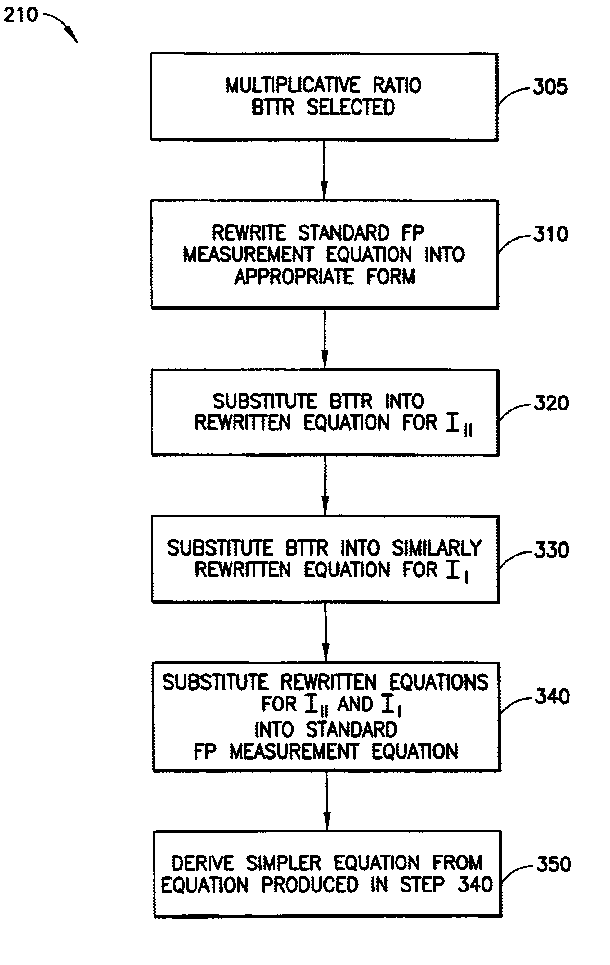
The method according to the present invention may be applied to the above equation, resulting in: ##EQU19##

Thus, the method according to the present invention may be applied to FA measurement equations to compensate for background fluorescence while maintaining both precision and accuracy.


PUM

PropertyMeasurementUnit
fluorescenceaaaaaaaaaa
fluorescence polarizationaaaaaaaaaa
fluorescence anistrophyaaaaaaaaaa

Abstract

A method in which a multiplicative ratio approach is used to remove the effects of the unwanted background fluorescence when making fluoroescence polarization (FP) measurements rather than the conventional subtractive approach, thus preserving both the precision and accuracy of the FP measurements, is disclosed. The method comprises selecting an appropriate multiplicative ratio, then calculating the selected multiplicative ratio using sample measurements. The calculated multiplicative ratio is multiplied by an appropriate value in a standard FP measurement equation or an appropriate value in an equation derived from a standard FP measurement equation. After this, the corrected FP measurement is calculated. When such multiplicative ratios are applied to the appropriate value or values in an FP measurement equation, the effects of background noise can be reduced without decreasing the precision of the FP measurements.

Description

1. Field of the InventionThis application relates generally to fluorescence polarization measurements and, in particular, to a method of correcting fluorescence polarization measurements for the effects of background noise.2. Description of the Related ArtFluorescence polarization (FP) measurements are used to detect molecular interaction, since molecular interaction typically leads to an increase in the polarization signal. See John C. Owicki, "Fluorescence Polarization and Anisotrophy in High Throughput Screening: Perspectives and Primer", JOURNAL OF BIOMOLECULAR SCREENING, Vol. 5, No. 5, 2000 (Hereinafter referred to as "FP / FA Primer", and incorporated by reference) for various examples of assays using fluorescence polarization.FIG. 1 shows a conventional FP Plate Reader which is used for taking FP measurements from samples in a microtitre plate. Plate 101 contains Samples 105 in Wells 110. Samples 105 are typically comprised of a cell preparation, buffers, a drug or other target...

Claims


Application Information

Patent Timeline
Patent Type & Authority Patents(United States)
IPC IPC(8): G01N21/64G01N21/25G01J3/44G01J3/28G01J3/447
CPCG01J3/44G01J3/4406G01N21/253G01N21/6445G01J3/447
Inventor HOYT, CLIFFORD C.
Owner CAMBRIDGE RES & INSTR
Why Eureka
Try Eureka