Wheel end system

a technology of end units and wheels, applied in the field of torque distribution systems in automotive vehicles, can solve the problems of increased weight, difficult installation of wheel end units on the side shaft of the vehicle, and expensive design considerations of prior art systems

Inactive Publication Date: 2004-01-13
GKN AUTOMOTIVE INC
View PDF6 Cites 7 Cited by
  • Summary
  • Abstract
  • Description
  • Claims
  • Application Information

AI Technical Summary

Benefits of technology

Still another object of the present invention is to provide a wheel end disconnect system that is easier to install, has a reduction in weight and provides for a more robust system and connection to a side shaft.
Still another object of the present invention is to provide a more simplified connection device between the side shaft of the drivetrain system and the spindle or wheel hub of the automotive vehicle.
Another advantage of the present invention is a wheel end system that has reduced weight.
Still another advantage of the present invention is a wheel end system that reduces installation time and complexity for manufacturers.
Still another advantage of the present invention is a more robust connection between a side shaft and the wheel end unit.
Still another advantage of the present invention is the reduced costs for the side shaft end.

Problems solved by technology

Furthermore, these prior art systems have expensive design considerations such as bearing sets and supports needed to have the hubs operate under all on and off road vehicle conditions while also being cognizant of vehicle operators desire for better gas mileage and quieter operation.
The prior art systems also have a problem with the side shaft connection to the wheel hub or spindle.
This long extension creates increased weight and also difficulty in inserting the wheel end unit onto the side shaft of the vehicle because of the angles and limited space available for installation procedures during manufacture of the vehicle.

Method used


Image

  • Wheel end system
  • Wheel end system
  • Wheel end system

Examples


Embodiment Construction

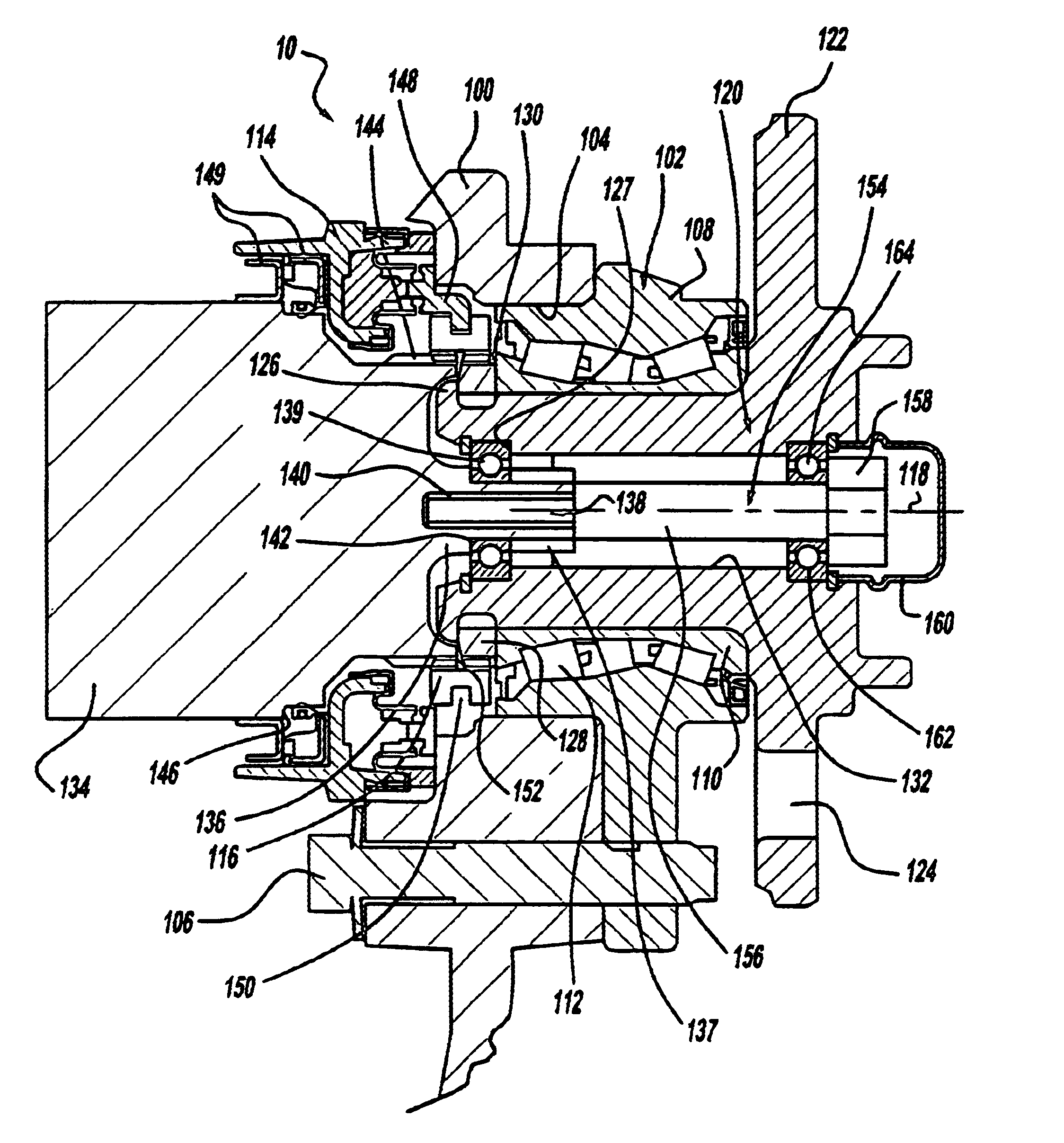
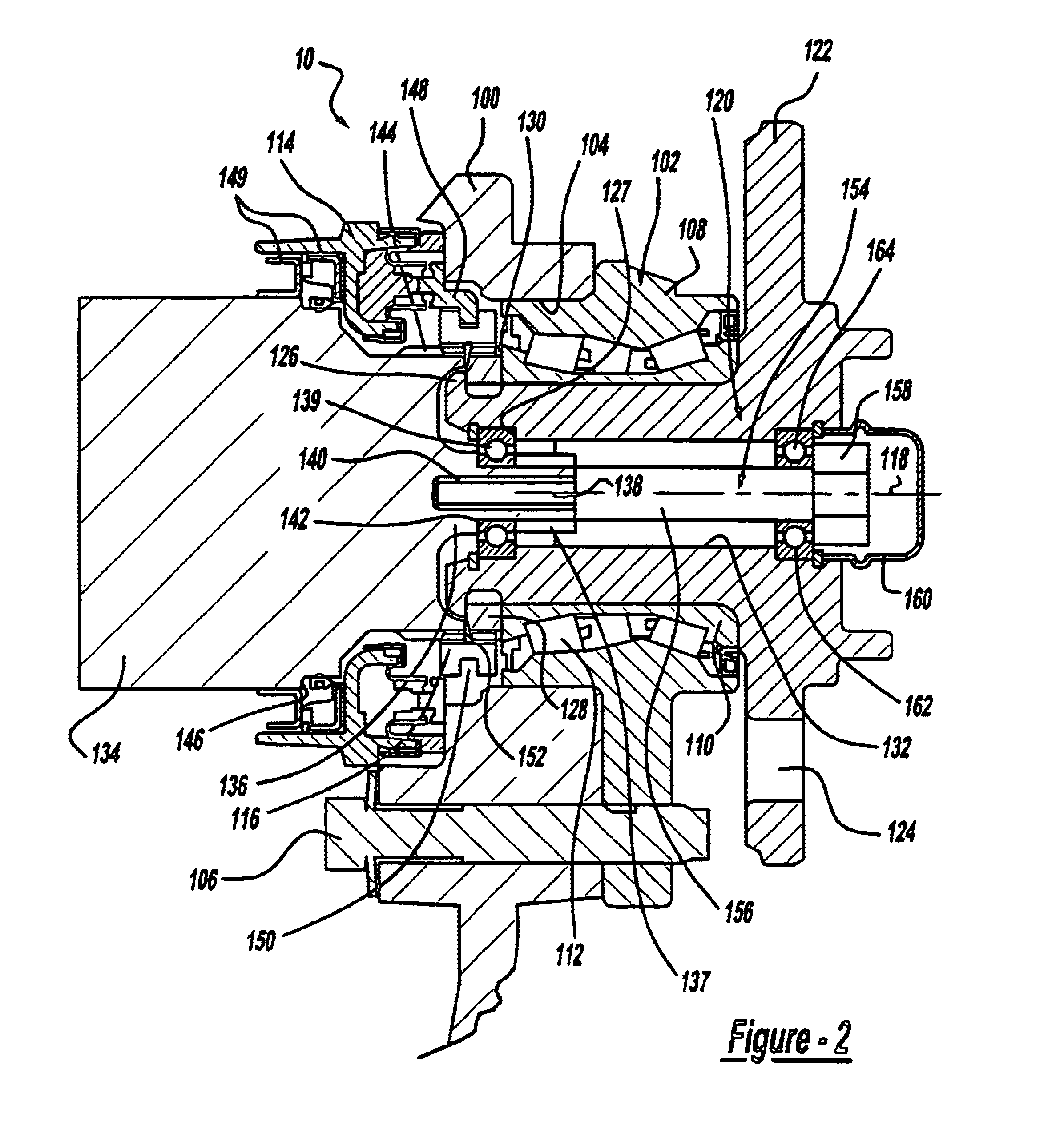
Referring to the drawings, a wheel end 10 for use on a vehicle is shown according to the present invention. Generally, a vehicle works when an engine sends power to a transmission which is then transferred to a transfer case and then distributed appropriately to either the front prop shaft or the rear prop shaft. From the front or rear prop shaft the power is transmitted to the front or rear differential and then onto the appropriate side shafts. Finally, the power is transferred onto the wheels through the wheel end units. Any number of configurations can be used for a drivetrain system such as torque being sent to only the front or rear axle, to both at a fixed percentage or one axle may be a hang on axle only receiving power when the other axle is in a slip condition. Furthermore, the transfer case generally is connected via a shift mechanism, that is operated by an operator of the automotive vehicle through any known selector, to provide power to or turn power off to the front w...


PUM


Abstract

A wheel end for use in a vehicle wherein the wheel end includes a side shaft wherein the side shaft having an appendage on one end thereof. The side shaft having a cylindrical cavity at a center point of the appendage. The wheel end unit also includes a spindle arranged around the appendage. A knuckle is arranged around a portion of the spindle and a portion of the side shaft. The wheel end also includes a fastener secured between the spindle and the appendage to ensure a robust connection between the spindle and the appendage.

Description

The present invention relates generally to wheel end systems for use in a vehicle, and more particularly relates to a wheel end disconnect system for use in an automotive vehicle.DESCRIPTION OF RELATED ARTTorque distribution systems in automotive vehicles have been known for many years. The torque distribution systems are designed for a variety of different vehicles such as rearwheel drive vehicles, front wheel drive vehicles, and even four wheel or all wheel drive vehicles, in the latter two configurations the front wheels and / or the rear wheels are engaged to be driven by the drivetrain as required. In an all wheel drive or four wheel drive vehicle torque maybe delivered to a wheel at a fixed percentage or in an on demand manner. There are currently known many types of engagement systems that will engage a wheel to the drivetrain thus sending torque to the wheel. In four wheel drive systems generally one axle either the front or rear is the primary driven axle. In most cases the r...

Claims


Application Information

Patent Timeline
Patent Type & Authority Patents(United States)
IPC IPC(8): B60B27/00B60K17/35B60K23/08G06Q50/34G07F17/32G07F17/34
CPCB60B27/00B60K17/3515B60K23/08G06Q50/34G07F17/32G07F17/3213G07F17/3234G07F17/3237G07F17/3241G07F17/3288Y02T10/86
Inventor HAHN, STEVEN C.
Owner GKN AUTOMOTIVE INC
Why Eureka
Try Eureka