Infrared touch panel with improved sunlight rejection

Inactive Publication Date: 2004-01-13
L 3 COMM CORP
View PDF23 Cites 268 Cited by
  • Summary
  • Abstract
  • Description
  • Claims
  • Application Information

AI Technical Summary

Problems solved by technology

However, it is the differences in the way that the various types of touch screens operate that causes a designer to use one type of touch screen over another for a particular application.
Disadvantageously, however, resistive touch screens can be easily damaged, exhibit poor display characteristics, and must typically be calibrated when ambient temperature changes by more than 40 degrees Fahrenheit.
Capacitive touch screens also provide high touch point density and low cost, but capacitive touch screens can be easily damaged, must be calibrated due to large temperature changes, and cannot be operated with a gloved hand.
However, surface acoustic wave touch screens typically exhibit the highest cost and can be falsely triggered by noise, wind, transmission signals, and insects.
Thus, it can be seen that these three types of touch screens are typically not well suited for outdoor use where it is desirable for touch screens to be operated by a gloved hand and to be resistant to damage and false triggering.
Although infrared touch screens are typically the most suitable type of touch screen to use in outdoor applications, high ambient light conditions, such as direct sunlight, can cause an infrared touch screen to malfunction.
High ambient light tends to saturate the light detectors and cause erratic operation of the touch screen.
Thus, high ambient light conditions can still trigger erratic operation.
The second mentioned technique of boosting the energy to the light emitting devices is similarly ineffective in high ambient light conditions, because the intensity of the sunlight spectrum tends to become greater than the intensity of the light produced by the light emitters.
Furthermore, such a light compensation scheme is hampered by the use of expensive light emitting and light detecting devices necessary to handle the increased energy requirements.
Finally, in regard to the third mentioned technique of using a structural member to shade the touch screen, it can be readily appreciated that such structures add to the overall cost of the system.
Also, in the case of small shrouds constructed to encompass only the touch screen, such shrouds can interfere with user operation and may be broken easily.

Method used


Image

  • Infrared touch panel with improved sunlight rejection
  • Infrared touch panel with improved sunlight rejection
  • Infrared touch panel with improved sunlight rejection

Examples


Embodiment Construction

One or more specific embodiments of the present invention will be described below. In an effort to provide a concise description of these embodiments, not all features of an actual implementation are described in the specification. It should be appreciated that in the development of any such actual implementation, as in any engineering or design project, numerous implementation-specific decisions must be made to achieve the developers' specific goals, such as compliance with system-related and business-related constraints, which may vary from one implementation to another. Moreover, it should be appreciated that such a development effort might be complex and time consuming, but would nevertheless be a routine undertaking of design, fabrication, and manufacture for those of ordinary skill having the benefit of this disclosure.

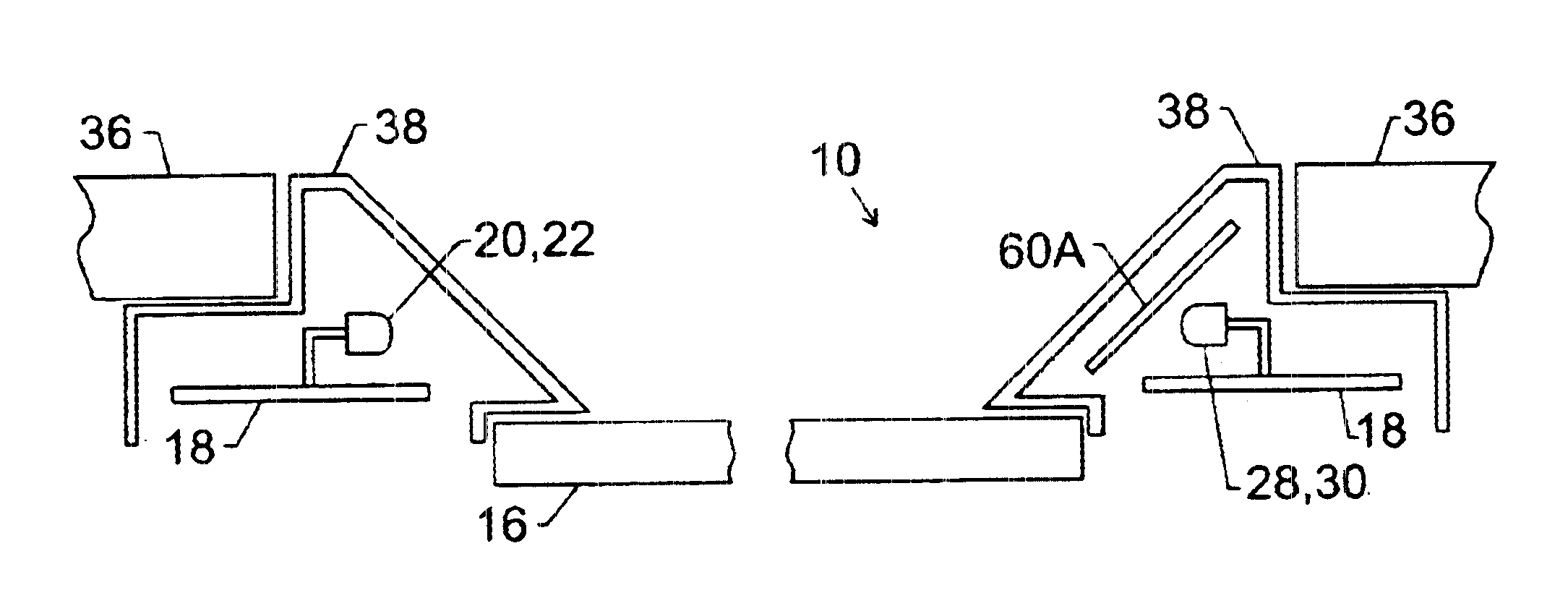
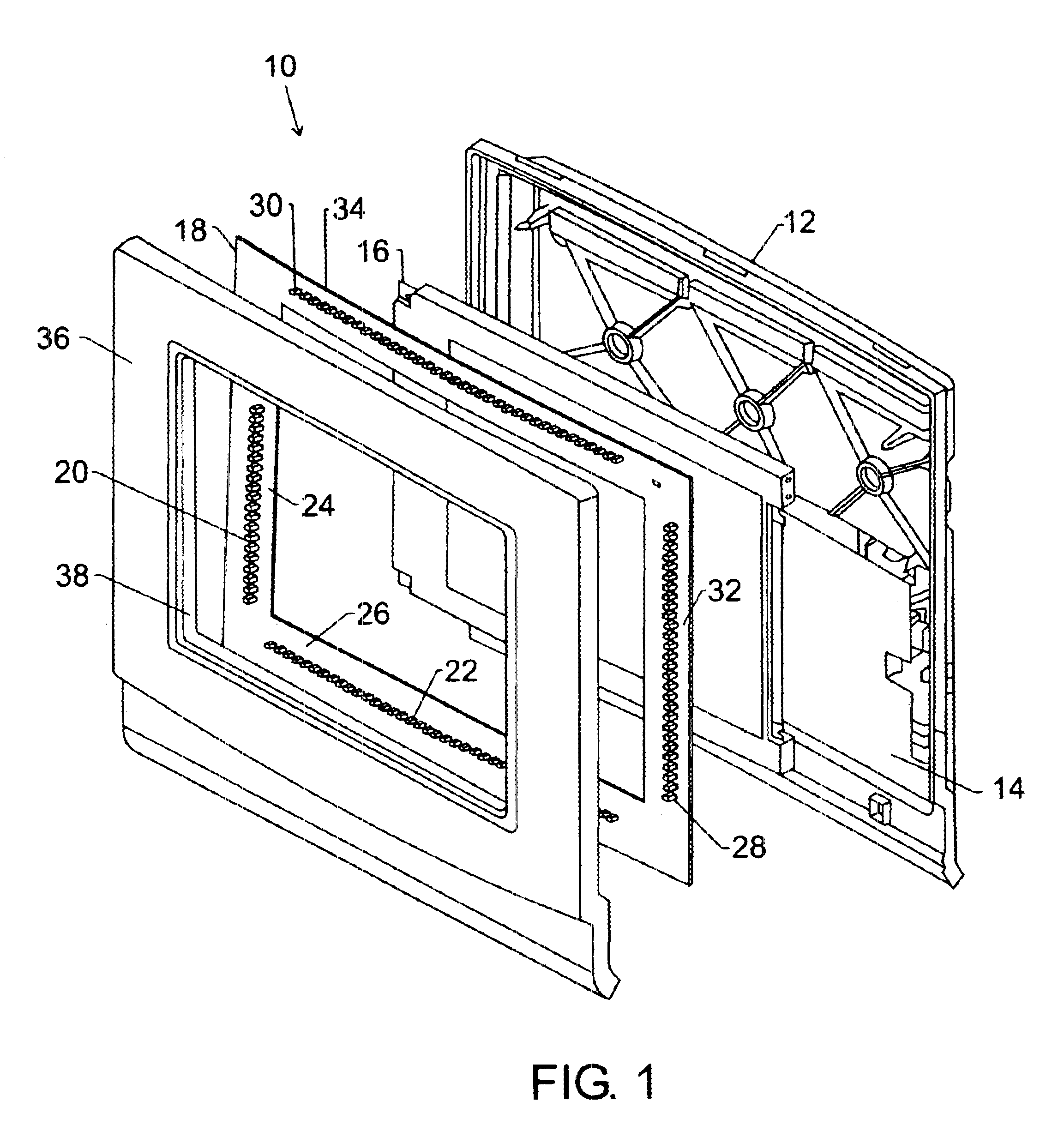
Turning now to the drawings, and referring initially to FIG. 1, a touch screen assembly is illustrated and generally designated by a reference numeral 10. The t...


PUM


Abstract

Ambient light can saturate the light detectors of a touch screen and cause unreliable operation. To address this concern, one or more filters may be placed proximate the detectors. A first filter may be a spatial filter, such as a microlouvre filter. A microlouvre filter is arranged so that it passes light transmitted by the light detectors and rejects off-axis light. Another filter may be a narrow band optical filter, such as a dichroic notch filter. Such an optical filter passes light having wavelengths within a narrow band selected to correspond to the spectral characteristics of the light emitters, while it rejects light of other wavelengths. The spatial filter and the narrow band optical filter may be used separately or in combination.

Description

1. Field of the InventionThe present invention relates generally to input devices and, more particularly, to improvements for touch panel displays.2. Background of the Related ArtThis section is intended to introduce the reader to various aspects of art that may be related to various aspects of the present invention which are described and / or claimed below. This discussion is believed to be helpful in providing the reader with background information to facilitate a better understanding of the various aspects of the present invention. Accordingly, it should be understood that these statements are to be read in this light, and not as admissions of prior art.Input devices perform the function of providing some means for entering commands and data into a computer, data processor, or information system. A variety of input devices are currently available, including keyboards, light pens, data tablets, mice, track balls, joysticks, scanners, voice recognition devices, and touch screens. Ea...

Claims


Application Information

Patent Timeline
IPC IPC(8): G09G5/00
CPCG06F3/0421
Inventor BLANCHARD, RANDALL D.
Owner L 3 COMM CORP
Why Eureka
Try Eureka