Construction perimeter guard

a construction and perimeter guard technology, applied in the direction of scaffold accessories, furniture parts, applications, etc., can solve the problems of time-consuming and laborious installation of construction perimeter guards about elevated floor slabs, excessive bending, stooping and manipulation of perimeter guard posts or stanchions, and poor leverage of workmen when tightening fastening elements

Inactive Publication Date: 2004-01-20
A 1 PLANK & SCAFFOLD MFG
View PDF12 Cites 78 Cited by
  • Summary
  • Abstract
  • Description
  • Claims
  • Application Information

AI Technical Summary

Problems solved by technology

In conventional systems the installation of perimeter guard posts or stanchions requires an excessive amount of bending, stooping and manipulation of fasteners beyond the outboard edge of a floor slab by the workmen who install the guard posts.
Fastening and clamping the fixtures in conventional construction perimeter guard systems require the workmen to perform tasks from awkward, dangerous positions.
Also, the components are situated so that the workmen have very poor leverage when tightening the fastening elements of the perimeter guard.
As a consequence, installation of a construction area perimeter guard about an elevated floor slab is quite time-consuming and labor-intensive.
Furthermore, fasteners are sometimes not tightened correctly due to the poor leverage that the installing workmen are able to exert and also due to fatigue from working in awkward positions.

Method used


Image

  • Construction perimeter guard
  • Construction perimeter guard
  • Construction perimeter guard

Examples


Embodiment Construction

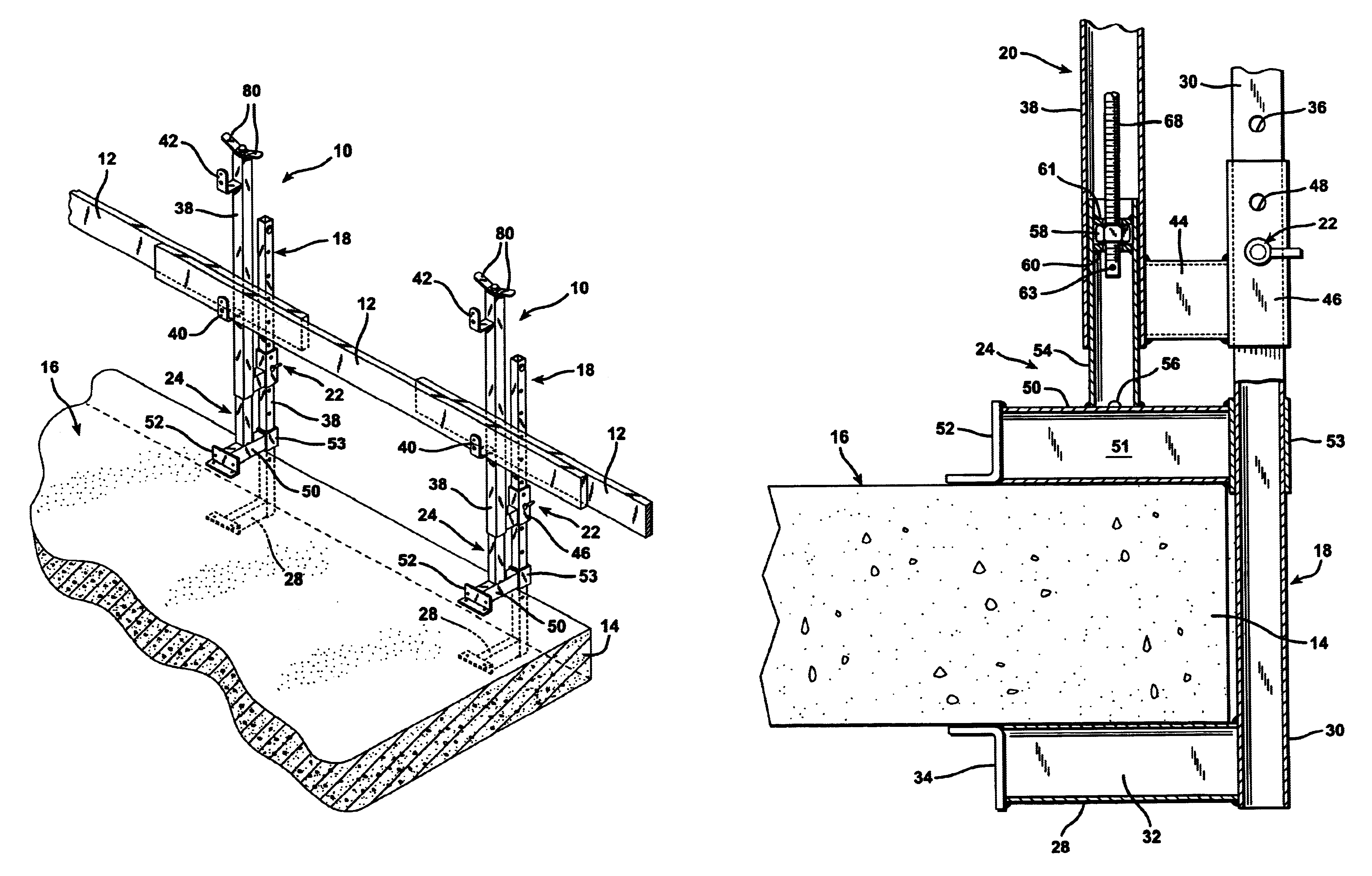
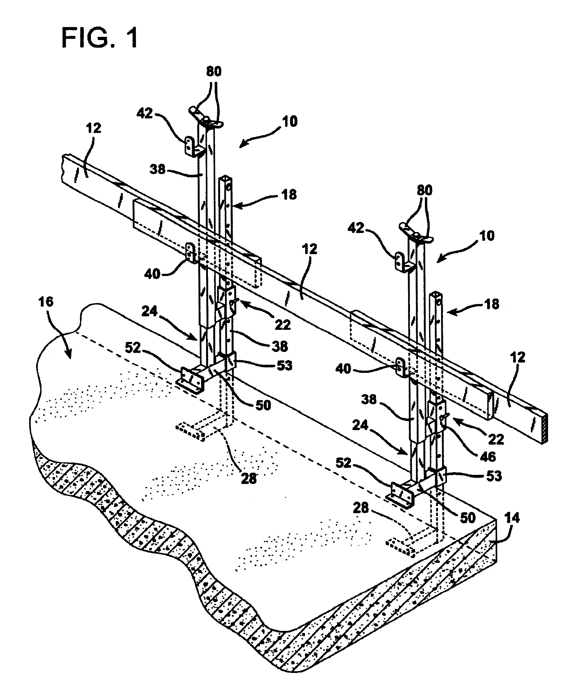
FIG. 1 illustrates a pair of transversely spaced construction perimeter guard stanchions 10 according to the invention supporting a plurality of transversely extending guard rail boards 12. The stanchions 10 are identical to each other in construction. The perimeter guard stanchions 10 are mounted upon the edge 14 of a concrete floor slab 16. The slab 16 is a typical section of slab flooring poured at a considerable height above grade in the construction of a multistory building.

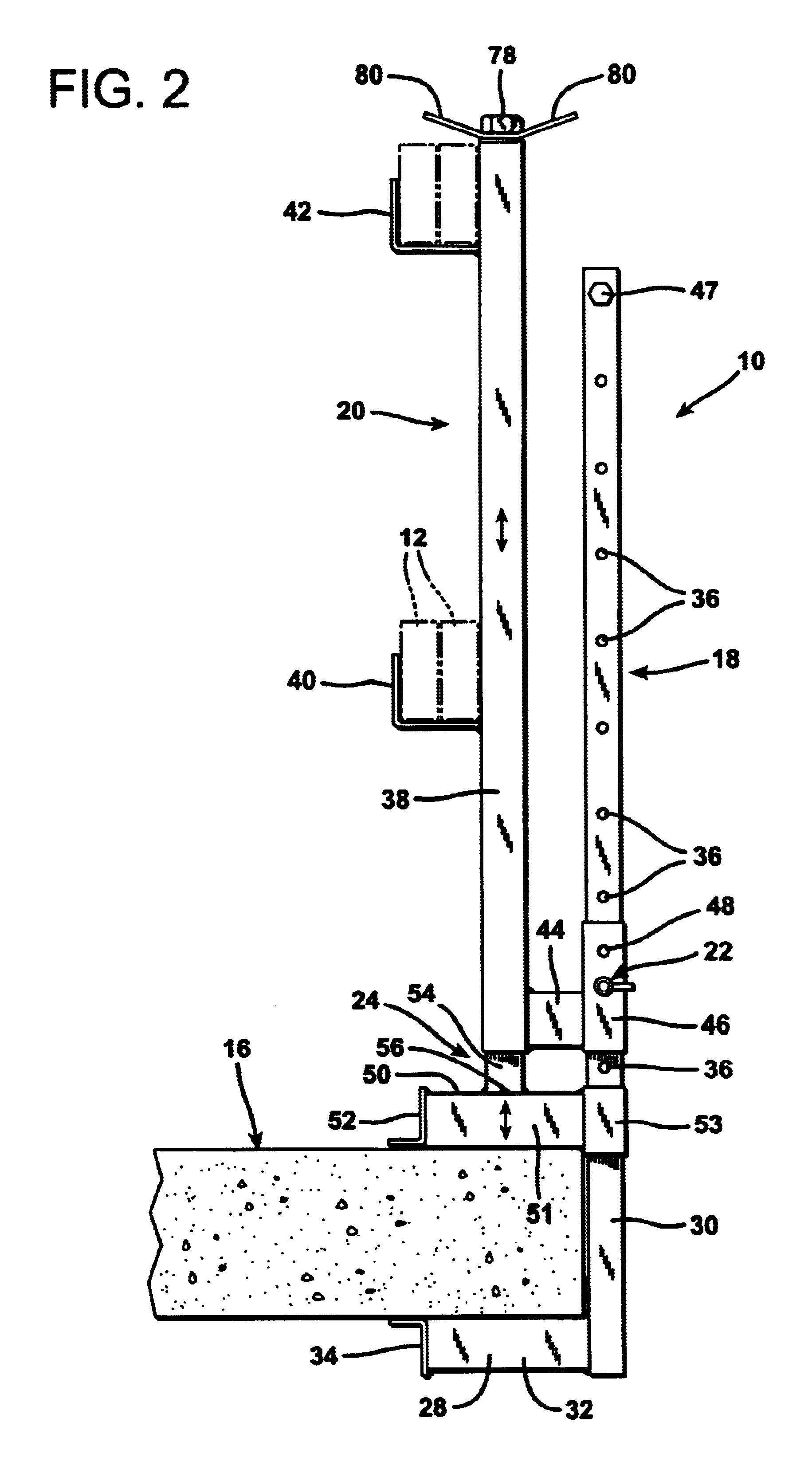
A single one of the stanchions 10 is illustrated in side elevation in FIG. 2. Each stanchion 10 is comprised of an outboard clamp element 18, an inboard support member 20, at least one locking pin 22, an inboard clamp element 24, and an elongated fine adjustment screw element 26, illustrated in isolation in FIG. 3.

The outboard clamp element 18 includes a horizontal lower, laterally projecting jaw 28 and an outboard vertical support member 30. The lower, laterally projecting jaw 28 is formed of a length of el...


PUM


Abstract

The present invention is an improved construction perimeter guard stanchion. A dual adjustment system performs both coarse and fine adjustments to tightly clamp a pair of jaws at the lower end of the stanchion upon the edge of a floor slab in an elevated, unfinished building structure. A coarse jaw adjustment sleeve formed of a short section of hollow steel tubing is coaxially disposed about an outboard support member in sliding engagement therewith. The coarse adjustment sleeve has one or more perforations therethrough so that a locking pin can be passed through it and through aligned openings in the outboard support member. A fine adjustment screw member is disposed coaxially within a vertical rail support tube and may be rotated by lever arms to move the upper jaw closer to or further from the lower jaw. Adjustment of the fine positioning mechanism is performed by manipulating handles at the top of the vertical rail support tube. A workman installing the stanchion thereby does not have to stoop over to operate a clamp located down near the concrete slab.

Description

1. Field of the InventionThe present invention relates to an assembly for holding guard rails at the peripheral edge of an elevated floor slab during construction of a multifloor building.2. Description of the Prior ArtIn the construction industry commercial, industrial and multiunit residential buildings are typically constructed with a framework formed of steel girders. As the framework for the various floor levels is formed, concrete floor slabs are poured so that the workmen on the project have floor support upon which to perform their tasks. Since the floor slabs are poured before the building walls are constructed it is important to create some type of perimeter guard at the edges of the floor slabs to prevent workmen from inadvertently falling off of the edge of a floor slab without realizing they are near the edge.For many years perimeter guards for floor slabs in a multistory building have been provided by installing temporary stanchions or posts at spaced intervals around ...

Claims


Application Information

Patent Timeline
Patent Type & Authority Patents(United States)
IPC IPC(8): E04G21/32
CPCE04G21/3233Y10S256/06E04G21/3242
Inventor ALLENBAUGH, DWIGHT
Owner A 1 PLANK & SCAFFOLD MFG
Why Eureka
Try Eureka