Structure and construction method of cast-in-site style welded steel frame composite concrete shear wall

A concrete shear wall, cast-in-place technology, applied in building structures, walls, building components, etc., can solve problems such as costing a huge amount of money, a lot of construction waste, and difficulty in solving linear thermal bridges at the floor, to improve stability. Effect

Active Publication Date: 2013-07-10
石家庄晶达建筑体系有限公司
View PDF3 Cites 40 Cited by
  • Summary
  • Abstract
  • Description
  • Claims
  • Application Information

AI Technical Summary

Problems solved by technology

[0002] The current thermal insulation form of the shear wall is mainly external thermal insulation. The design service life of the thermal insulation layer is only half of the main structure. It needs to be maintained and replaced many times in the whole life cycle of the building, which will generate a lot of construction waste and cost a huge amount of money. Seriously affect the function of use
In addition, most of the external insulation is made of combustible materials, which poses a huge fire hazard
Moreover, the traditional external insulation construction is all manual operation, the quality stability is low, and it cannot meet the development trend of building factoryization
In the emerging composite thermal insulation technology, the cast-in-place composite concrete wall technology is difficult to control the position of the thermal insulation layer and the section size of the stressed wall, the linear thermal bridge at the floor is difficult to solve, the casing through the wall is prone to water seepage, and the force transmission path of the welded steel grid is not good. Technical problems such as clarification and no minimum requirements for the durability and fire resistance of the outer concrete layer hinder the widespread implementation of composite insulation

Method used


Image

  • Structure and construction method of cast-in-site style welded steel frame composite concrete shear wall
  • Structure and construction method of cast-in-site style welded steel frame composite concrete shear wall
  • Structure and construction method of cast-in-site style welded steel frame composite concrete shear wall

Examples


Embodiment Construction

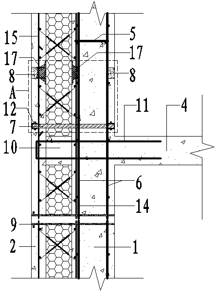
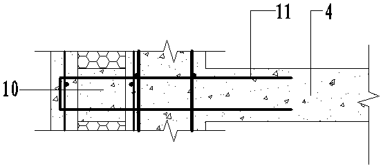
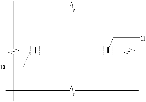
[0039] The present invention is a structure of a cast-in-place welded grid frame composite concrete shear wall, and plastic pads are arranged between the welded steel grids on both sides and the insulation board to control the position of the insulation layer well; The cross-sectional size of the composite wall; the method of setting cantilevered holes and cantilevered steel bars at the floor slab solves the problem of linear thermal bridges at the floor slab; the non-combustible pipe with a water-stop ring on the outside is used for the wall-through casing to avoid the phenomenon of water seepage ;By controlling the diameter, slenderness ratio, angle, etc. of the obliquely inserted steel bar, the stability of the obliquely inserted steel bar is improved, so that it can transmit the external forces of different directions borne by the thinner side concrete layer to the thicker side concrete layer; strict Control the thickness of the concrete on both sides and the material and p...


PUM

PropertyMeasurementUnit
heightaaaaaaaaaa
widthaaaaaaaaaa
heightaaaaaaaaaa

Abstract

The invention relates to a structure and a construction method of a cast-in-style welded steel frame composite concrete shear wall. The structure comprises an indoor concrete layer, an outdoor concrete layer and a wire frame insulation sandwich board. The wire frane insulation sandwich board is coated between the indoor concrete layer and the outdoor concrete layer. At least two rectangular and groove-typed cantilever holes are arranged at the top of the sandwich board, and each cantilever hole is provided with a U-shaped cantilever anchor bar which penetrates through the sandwich board and a floor slab to be fixedly connected with the floor slab. The construction method includes site preparation work, binding of load-bearing steel bars of a wall body and edge member steel bars, custom processing of the sandwich boards, installation of the sandwich boards, pavement of template positioning pieces and wall bushings, fixation of water and electric pipes inside the wall body, binding of ordinary blocks on both sides of the wall body steel bars, erecting of the templates, pouring of the concrete, removing of the templates and concrete curing. Since a series of composite wall construction methods are adopted, problems existing in the prior art are solved, and a composite heat preservation technology is improved.

Description

technical field [0001] The invention relates to the field of building construction, in particular to a structure and a construction method of a cast-in-place welded grid frame composite concrete shear wall. Background technique [0002] The current thermal insulation form of the shear wall is mainly external thermal insulation. The design service life of the thermal insulation layer is only half of the main structure. It needs to be maintained and replaced many times in the whole life cycle of the building, which will generate a lot of construction waste and cost a huge amount of money. Seriously affect the function of use. In addition, most of the external insulation is made of combustible materials, which poses a huge fire hazard. Moreover, the traditional external thermal insulation construction is all manual operation, the quality stability is low, and it cannot meet the development trend of building factoryization. In the emerging composite thermal insulation technolo...

Claims


Application Information

Patent Timeline
Patent Type & Authority Applications(China)
IPC IPC(8): E04B2/84E04G21/00
Inventor 张晶廷李云峰张霞
Owner 石家庄晶达建筑体系有限公司
Why Eureka
Try Eureka