Low loss cable coupler

a low-loss, cable coupler technology, applied in the direction of cable junctions, electric cable installations, coupling device connections, etc., can solve the problems of significant loss of insertion from a conventional center conductor contacting co-axial cable coupler, prohibitively expensive type of coupler, and significant impedance discontinuity of axial cable coupler with mismatch loss

Inactive Publication Date: 2004-01-27
ANDREW CORP
View PDF14 Cites 43 Cited by
  • Summary
  • Abstract
  • Description
  • Claims
  • Application Information

AI Technical Summary

Benefits of technology

A capacitor assembly 100 with an insulating substrate 110, for example a printed circuit board, may be used, as shown in FIG. 2. A range of capacitors each having different capacitance values, mounted on different insulating substrates 110 allows field selection of the capacitance value providing best performance with respect to the characteristics of trunk cable 1 and a desired operating frequency. Different values of capacitance may be easily and quickly applied by substituting different capacitor assemblies 100, for example designed in a cartridge configuration dimensioned for easy insertion into the aperture in the outer conductor 20, each capacitor assembly 100 having a different value capacitor 80 mounted thereon / therein.
As described, the low loss coupler provides the following advantages. The low loss coupler has a reduced insertion loss. The low loss cable coupler is tunable through the use of different capacitive inserts or parasitic capacitance dielectric spacers. Existing conventional center conductor contacting cable couplers and their cover assemblies may be adapted according to the invention with a minimum of required modifications.

Problems solved by technology

The contact pin of a conventional co-axial cable coupler creates a significant impedance discontinuity with mismatch loss.
Where energy conservation is desired, or multiple couplers are required, the insertion loss from a conventional center conductor contacting co-axial cable coupler may be significant.
However, these devices mount impedance transformers and or reactive components on a printed circuit board mounted in a coupler cover assembly.
However, these devices require cutting the trunk cable at a desired insertion point, installing connectors at both sides of the break and insertion of the coupler, in-line.
The separate structure of the coupler, required connectors and time-consuming installation procedure may cause this type of coupler to be prohibitively expensive.

Method used


Image

  • Low loss cable coupler
  • Low loss cable coupler
  • Low loss cable coupler

Examples


Embodiment Construction

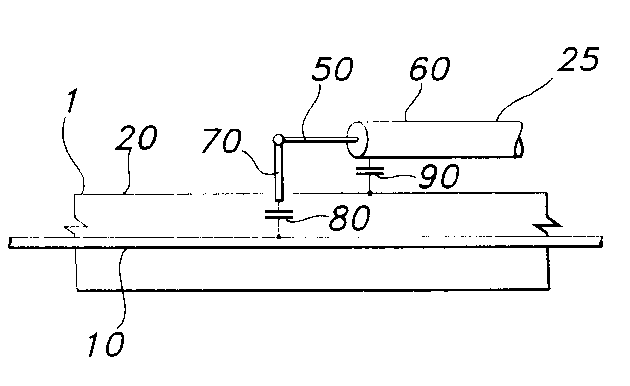
As shown in FIG. 1, RF energy in a trunk cable 1 propagates in a space between a center conductor 10 and a surrounding outer conductor 20. To couple the RF energy into a second cable 25 having a second center conductor 50 and a second outer conductor 60, a probe 70 coupled with the second center conductor 50 is inserted through an aperture in the outer conductor 20, into mechanical contact with the center conductor 10. To minimize an impedance discontinuity as a result of contact by the probe 70 with the center conductor 10, a capacitor 80 may be located in-line between the center conductor 10 and second center conductor 50, on or along the probe 70, at a location between the center conductor 10 and the aperture in the outer conductor 20. The outer conductor 20 and the second outer conductor 60 may be coupled together directly or capacitively coupled by proximity or a second capacitor 90.

The capacitor 80 may be, for example, an approximately 1.0 picofarad capacitor. Various differen...


PUM


Abstract

A cable coupler between a trunk cable having a first center conductor and a first outer conductor and a second cable having a second center conductor and a second outer conductor. An aperture is formed in the first outer conductor; a probe having a capacitive element on a first end is inserted into the aperture to contact the first center conductor. A second end of the probe is coupled to the second center conductor. The first outer conductor and the second outer conductor may be coupled together directly or via a second capacitor. A cover may be added to secure the different components and or to provide environmental protection for the cable coupler. The capacitive element may be mounted on an insulating substrate. A range of capacitive elements may be used to achieve a desired coupling between the trunk cable and the second cable.

Description

BACKGROUND OF INVENTION1. Field of the InventionThe invention relates to electrical cable couplers. More specifically, the invention relates to a "Piggy back" cable coupler with low insertion losses.2. Description of Related ArtMany systems, for example in--building RF distribution systems or antenna arrays, utilize a trunk cable from which multiple connections, taps, are made. "Piggy back" type cable couplers permit the diversion of a signal from a trunk cable to a second cable, without requiring cutting of the trunk cable and installation of connectors.Conventional "Piggy back " co-axial cable couplers introduce a contact pin through an aperture created in the trunk cable's outer conductor that contacts the trunk cable's center conductor. The contact pin of a conventional co-axial cable coupler creates a significant impedance discontinuity with mismatch loss. The mismatch loss, radiation and coupled energy losses, of a for example 10 dB coupler, may create an insertion loss of up ...

Claims


Application Information

Patent Timeline
Patent Type & Authority Patents(United States)
IPC IPC(8): H01R9/05H01R13/66
CPCH01R9/0509H01R13/6625
Inventor GUNNELS, ROBERT
Owner ANDREW CORP
Why Eureka
Try Eureka