System and method for minimizing dissipation in RF power amplifiers

a power amplifier and dissipation system technology, applied in the direction of push-pull amplifiers, phase splitters, gain control, etc., can solve the problems of higher maximum linear output, higher distortion limit, trade-off problems

Inactive Publication Date: 2004-01-27
GATESAIR
View PDF8 Cites 45 Cited by
  • Summary
  • Abstract
  • Description
  • Claims
  • Application Information

AI Technical Summary

Problems solved by technology

The trade-off problem is made more acute when the amplifier is to be designed for high peak to average signal conditions, such as those found in Trellis Coded 8-Level Vestigial Side Band ("8VSB") and / or Coded Orthogonal Frequency Division Multiplexing ("COFDM") television transmitters.
A lower output load line impedance and a higher amplifier supply voltage typically result in a higher maximum linear output (i.e., a higher distortion limit), all other factors being relatively constant.
As a result, the output signal average power is well below the amplifier's maximum linear power capability therefore resulting in a low amplifier efficiency.
One drawback of a low amplifier efficiency is that the amplifier must dissipate the excess power as heat.
Low amplifier efficiencies require cooling systems with a higher heat transfer capacity, and therefore higher cost, in order to prevent overheating and subsequent failure of the amplifier.
In the case where the load line impedance is lower for the same average output power, the amplifier is being supplied with more supply voltage than required by the amplifier resulting in an increase in excess power and a decrease in the efficiency of the amplifier.

Method used


Image

  • System and method for minimizing dissipation in RF power amplifiers
  • System and method for minimizing dissipation in RF power amplifiers
  • System and method for minimizing dissipation in RF power amplifiers

Examples


second embodiment

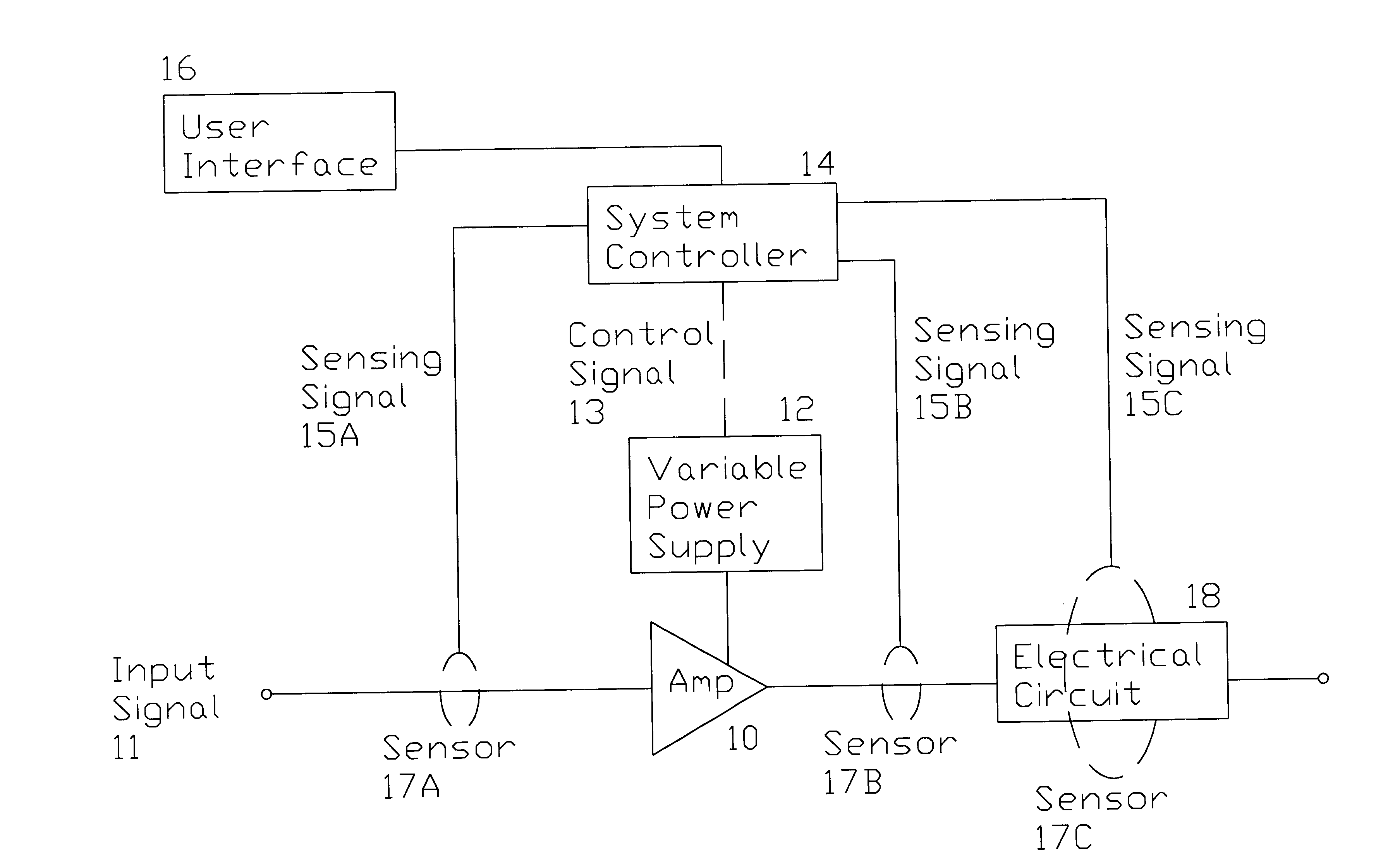
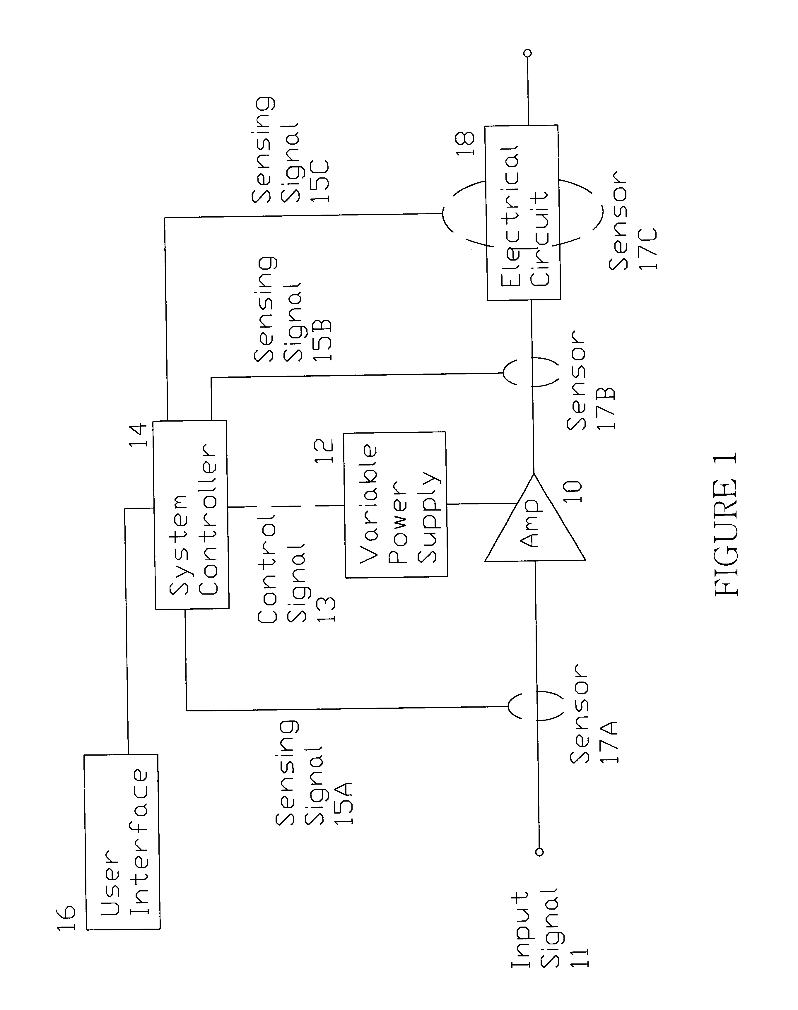
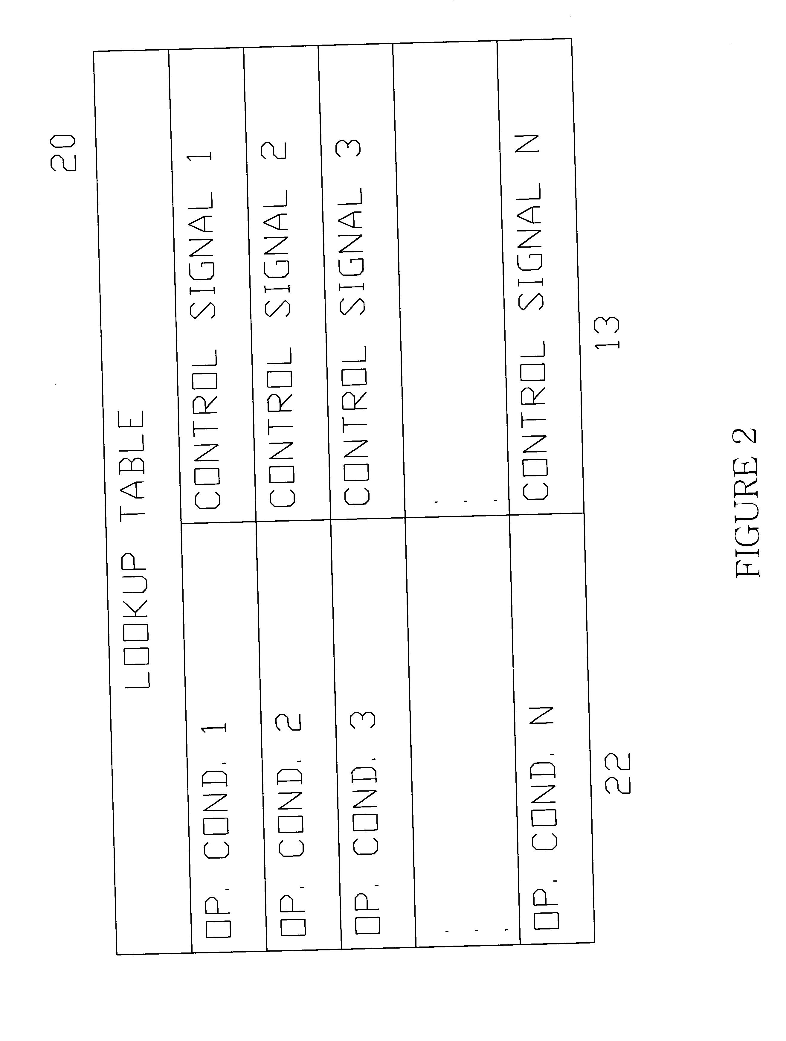
With reference now to FIG. 3, where like numerals represent like components in FIG. 1, which operate in a like manner, the invention is shown where the amplifiers 10-1 through 10-N are arranged in a cascaded series. A plurality of amplifiers is contemplated in the cascaded series shown, such as two amplifiers, three amplifiers, etc. In this embodiment, the variable power supply 12 is shown as supplying power to each of the cascaded amplifiers. The system controller 14, which preferentially comprises sensing means including a lookup table as described above, receives the sensing signals 15D and 15C. The sensing signal 15D may originate from one or more of the sensors 17N. Only one of the sensors 17N is labeled in FIG. 3 for clarity, but it is to be understood that the sensing signal 15D may originate from any of the sensors 17N shown immediately preceding or following one of the cascaded amplifiers 10-1 through 10-N. Sensing signal 15C may originate from the sensor 17C sensing the op...

third embodiment

With reference now to FIG. 4, where like numerals represent like components in FIGS. 1 and 3, which operate in a like manner, the invention is shown where the amplifiers 10-1 through 10-N are arranged in a cascaded series. A plurality of amplifiers is contemplated in the cascaded series shown, such as two amplifiers, three amplifiers, etc. In this embodiment, a one of variable power supply 12-1 through 12-N is associated with each one of the amplifiers 10-1 through 10-N, respectively, as shown. The system controller 14, which preferentially comprises sensing means including at least one lookup table as described above, receives the sensing signals 15D and 15C. As described above in the description of FIG. 3, the sensing signal 15D may originate from one or more of the sensors 17N. Only one of the sensors 17N is labeled in FIG. 4 for clarity, but it is to be understood that the sensing signal 15D may originate from any of the sensors 17N shown immediately preceding or following one o...

fourth embodiment

With reference now to FIG. 5, where like numerals represent like components in FIGS. 1, 3, and 4 which operate in a like manner, the invention is shown where the amplifiers 10-1 through 10-N are arranged in a parallel cascade. A plurality of amplifiers is contemplated in the parallel cascade shown, such as two amplifiers, three amplifiers, etc. In this embodiment, the variable power supply 12 is shown as supplying power to each of the parallel cascade of the amplifiers 10-1 through 10-N as shown. It is to be understood that the present invention also contemplates an individual variable power supply for each of the amplifiers 10-1 through 10-N, similar to the arrangement shown in the embodiment in FIG. 4. The embodiment with a plurality of variable power supply / amplifier pairs in a parallel cascade is not shown but may be inferred from this description.

The system controller 14, which preferentially comprises sensing means including at least one lookup table as described above, receiv...


PUM


Abstract

The variable power supply to an amplifier in an electrical circuit is dynamically controlled through the use of a lookup table responsive to one or more operating conditions of the electrical circuit. The lookup table is indexed by one or more of the operating conditions and the amount of amplification to be applied to an input signal to the amplifier is determined. One embodiment of the invention comprises a television transmitter circuit including a power amplifier circuit capable of amplifying a variable frequency COFDM or 8VSB input signal where the amount of amplification applied to the input signal is dynamically controlled through the use of a lookup table as a function of the frequency of the input signal.

Description

BACKGROUND OF THE INVENTIONThe design of radio frequency ("RF") power amplifiers is typically accomplished by taking into account the expected operating environment of the amplifier and the desired output characteristics of the amplifier, such as the output load line impedance. There are usually interrelated yet contradictory requirements that must be taken into account in setting the output load line impedance and trade-offs must be made that affect the performance of the amplifier. Some of the factors to be considered in setting the output load line impedance are output peak and average signal requirements, distortion limits, efficiency requirements, and the available power supply voltage. The trade-off problem is made more acute when the amplifier is to be designed for high peak to average signal conditions, such as those found in Trellis Coded 8-Level Vestigial Side Band ("8VSB") and / or Coded Orthogonal Frequency Division Multiplexing ("COFDM") television transmitters.For instan...

Claims


Application Information

Patent Timeline
Patent Type & Authority Patents(United States)
IPC IPC(8): H03G3/00H03G3/30H03F1/02H03F3/21
CPCH03F1/0222H03F1/0233H03F1/0244H03F1/0277H03F3/211H03G3/004H03G3/3042H03G2201/103H03G2201/504H03G2201/508H03G2201/702
Inventor POGGI, PETER JOHNDITTMER, TIMCABRERA, GEORGE
Owner GATESAIR
Why Eureka
Try Eureka