Method and device for co-operative radio direction-finding in transmission

Inactive Publication Date: 2004-02-17
THALES SA
View PDF11 Cites 8 Cited by
  • Summary
  • Abstract
  • Description
  • Claims
  • Application Information

AI Technical Summary

Problems solved by technology

While the prior art method performs well, it nevertheless has certain drawbacks.

Method used


Image

  • Method and device for co-operative radio direction-finding in transmission
  • Method and device for co-operative radio direction-finding in transmission
  • Method and device for co-operative radio direction-finding in transmission

Examples


examples of implementation

OF THE METHOD ACCORDING TO THE INVENTOIN

FIG. 11 shows the results obtained with two plane arrays of N=5 sensors, comprising one circular array with a radius of R=21.1 cm and one "V" shaped array . The azimuth .theta. is the incidence of a source in the plane of the array and the elevation angle .DELTA. is the incidence with respect to the perpendicular of the plane of the array. For the simulations in (.theta., .DELTA.), the direction-finding is done according to the parameters (u,v) which are the components of the wave vector of the source in the plane of the array. This components may be expressed in the form:

u=cos(.DELTA.) cos(.theta.) and v=cos(.DELTA.) sin(.theta.) (30)

The two arrays are adapted to the frequency range 900 MHz-1 GHz of the GSM. In the simulations, the center frequency is equal to f.sub.ant =900 Mhz and thus the wavelength is equal to .lambda.=c / f.sub.ant =33.33 cm.

The direction-finding performance characteristics will then be estimated, either with respect to th...


PUM


Abstract

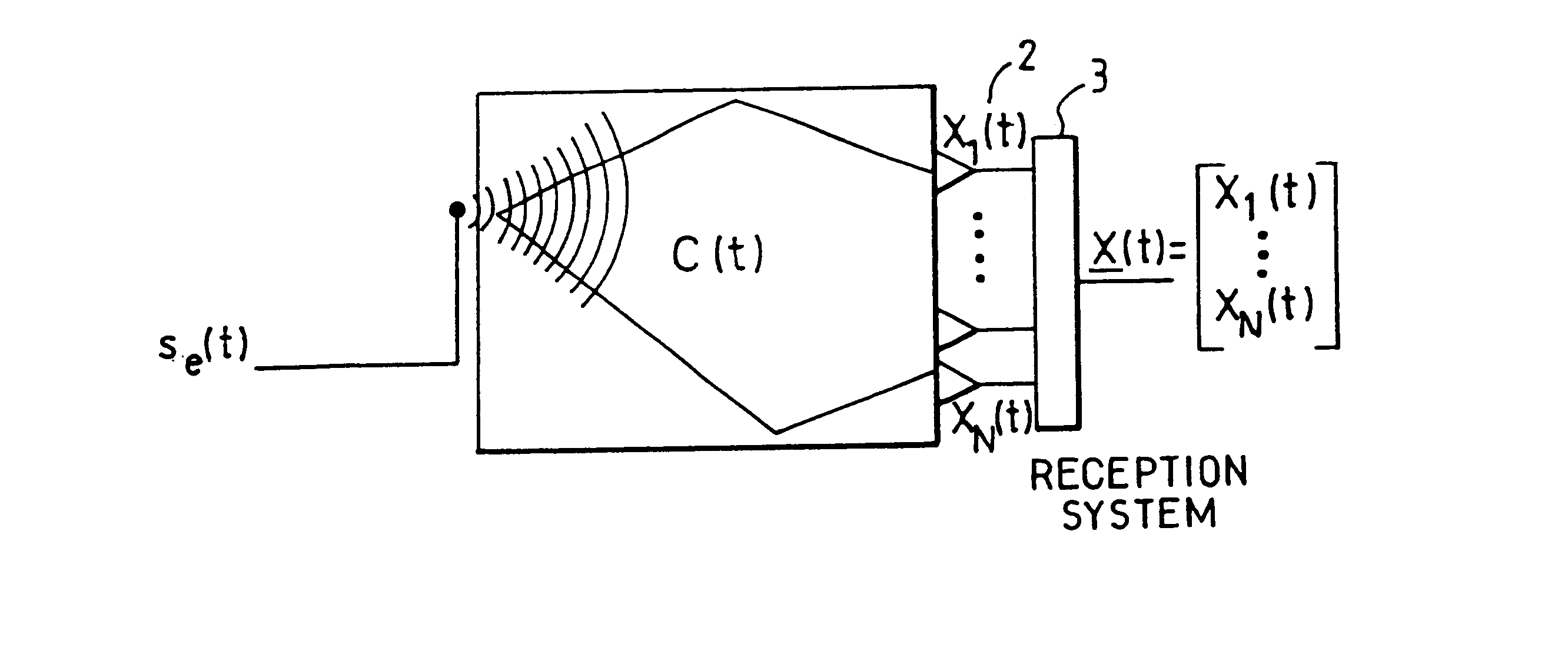
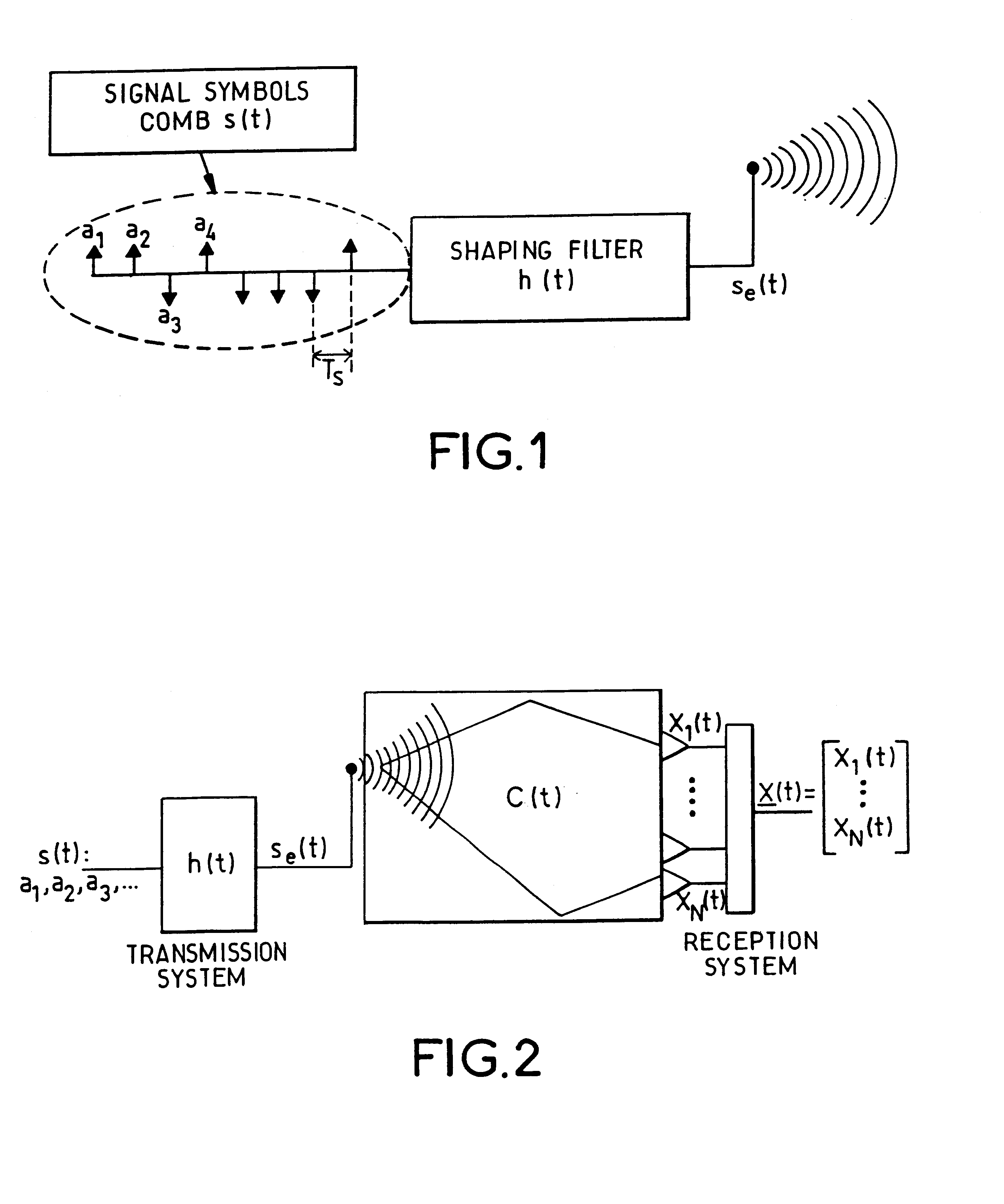
In a method of co-operative radio direction-finding in transmission in a system of radio direction-finding for a radiocommunications system comprising one or more transmission sources or transmitters, the transmitted signal comprises a reference sequence formed by a sequence of symbols {Sk}, the receiver comprising at least one array of several sensors coupled to a radio direction-finder. The method comprises the following steps:a) determining the reference signal or signals di(t) associated with a transmitter m from the reference symbols {Sk} and from the modulation defined by the format of the signals; b) defining the instant of arrival tk of one or more reference signals; c) from the signal x(t) received at the sensors, the instants of arrival tk and the reference signal or signals di(t) derived from the step a), determining the value or values of incidence of the signals for a given transmitter. The method can be applied to GSM or UMTS signals.

Description

1. Field of the InventionThe present invention relates to a method and a device for co-operative radio direction-finding in transmission for signals comprising a reference signal.The invention can be applied especially to the case of signals comprising a synchronization signal or reference signal, consisting of a sequence of known symbols defined by the transmission standard used within the transmission system.For example, the GSM (Global System for Mobile communications), consisting of several reference signals, has this characteristic. In such a context, a reception system such as a base station may perform a selective direction-finding operation and associate a direction of arrival with a synchronization sequence. The techniques of selective direction-finding can be used to isolate one transmitter from the others on the basis of knowledge of its reference signal. It is thus possible to carry out a selective direction-finding operation for the transmitter, thus reducing the risk o...

Claims


Application Information

Patent Timeline
Patent Type & Authority Patents(United States)
IPC IPC(8): G01S3/02G01S3/74
CPCG01S3/74
Inventor FERREOL, ANNEDELAVEAU, FRAN.CEDILLA.OIS
Owner THALES SA
Why Eureka
Try Eureka