Structure for load detection element in vehicle seat

a technology for vehicle seats and load detection elements, applied in the direction of roofs, instruments, tractors, etc., can solve the problem of limiting the range of fore-and-aft movement of the upper rail slidingly movable, and achieve the effect of reducing the sliding movement rang

Inactive Publication Date: 2004-02-24
TACHI S CO LTD
View PDF18 Cites 50 Cited by
  • Summary
  • Abstract
  • Description
  • Claims
  • Application Information

AI Technical Summary

Problems solved by technology

However, the riveted ends of the rivet pins which project in the lower rail, which undesirably l...

Method used


Image

  • Structure for load detection element in vehicle seat
  • Structure for load detection element in vehicle seat
  • Structure for load detection element in vehicle seat

Examples


Embodiment Construction

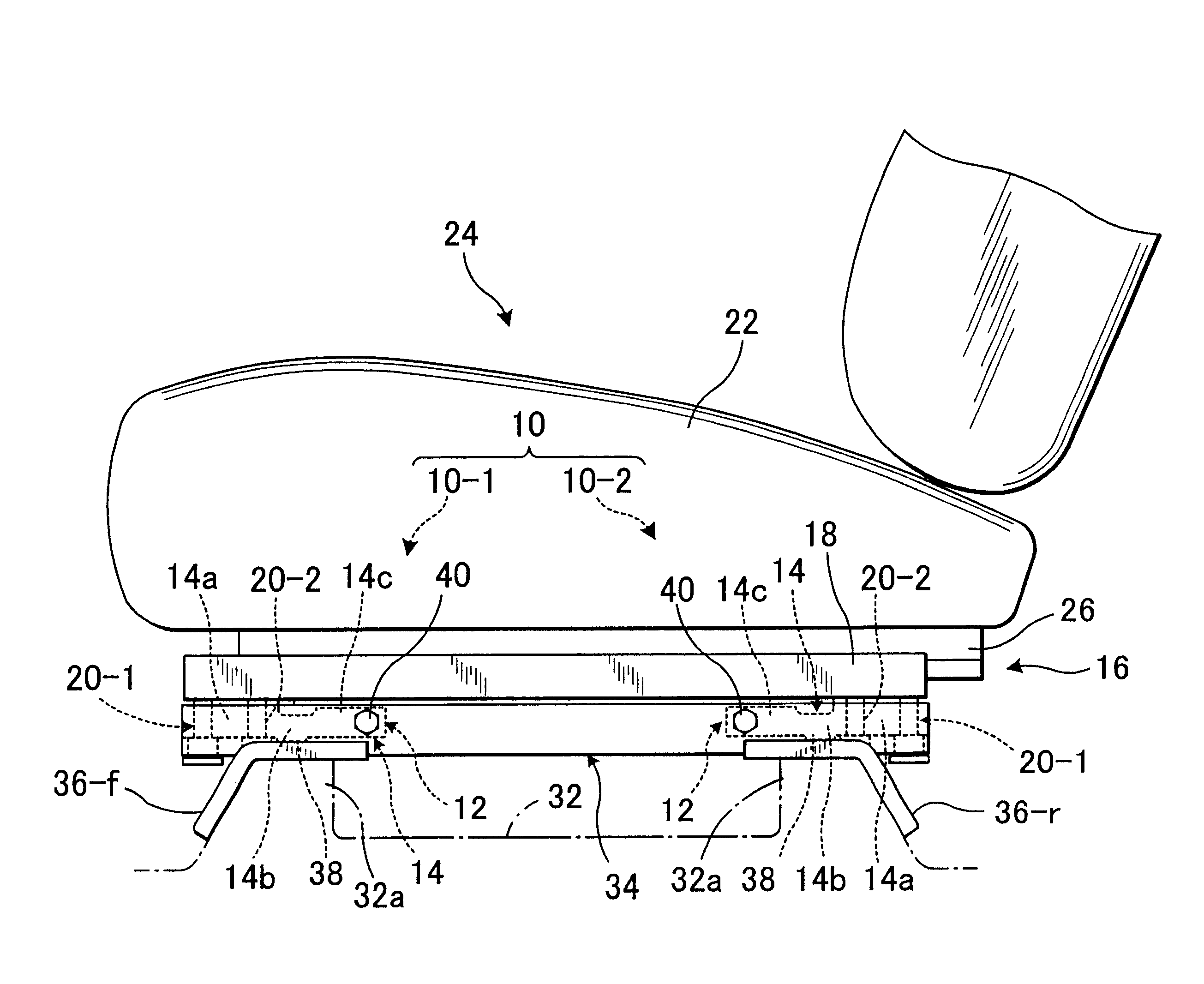
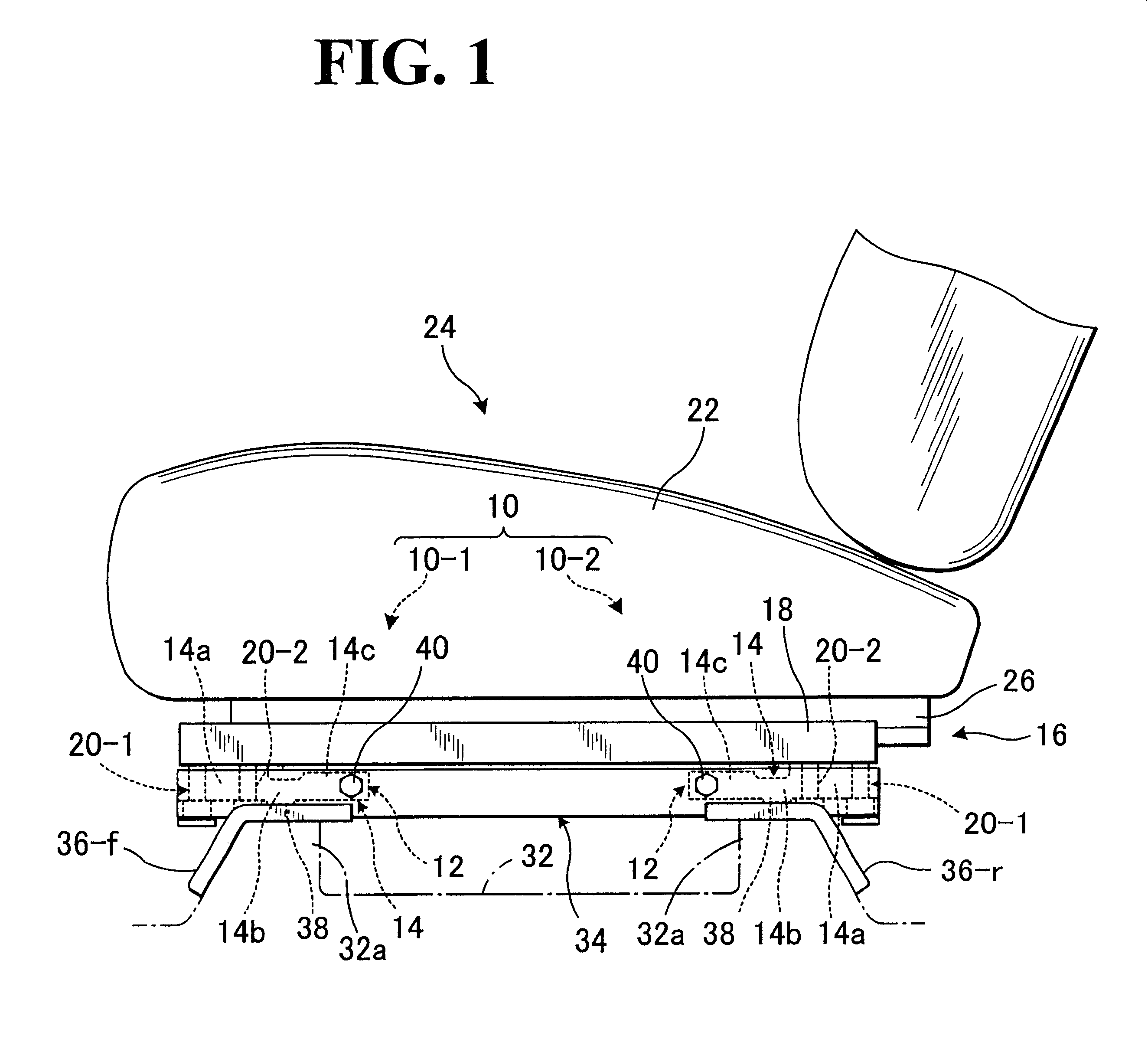
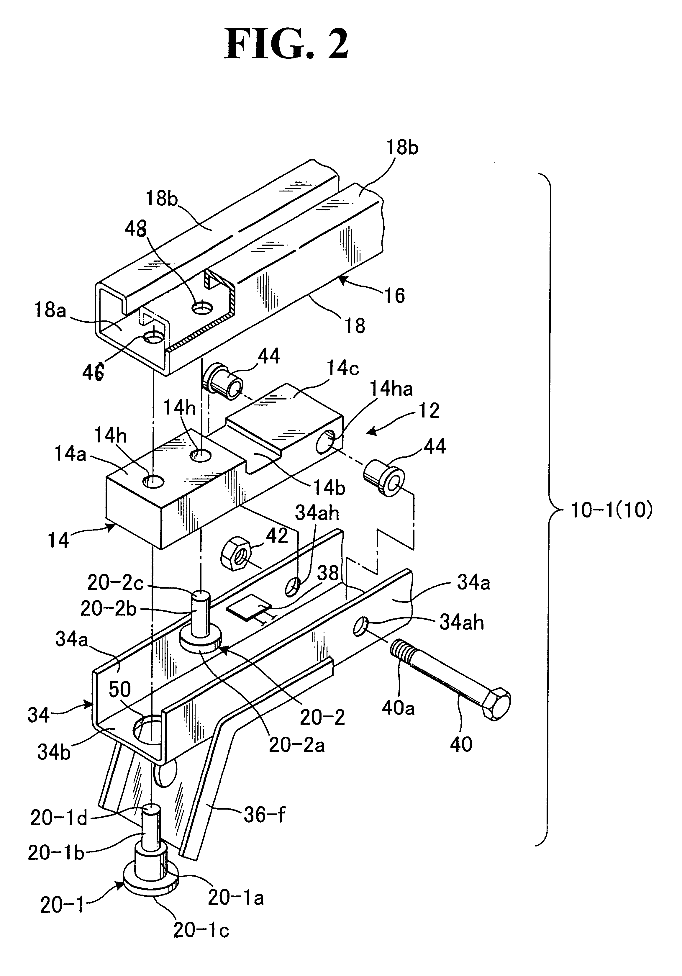
Referring to FIGS. 1 through 4, there is illustrated one preferred mode of structure for securing a load detection means in a vehicle seat in accordance with the present invention. Reference is first made to FIG. 1 in which designation (10) generally represents a structure for securing a load detection means between a slide rail device (16) and a support leg member (34) in a novel simplified manner. This structure shall be simply referred to as "securing structure" hereinafter.

As is known, the slide rail device (16) comprises a stationary lower rail (18) to be fixed on a floor (32) of a vehicle (not shown) and a movable upper rail (26) slidably fitted in and along the lower rail (18). The typical configuration of such slide rail device (16) is shown in the figures, wherein the movable upper rail (26) is of a generally inverted-T-shape cross-section which is slidably accommodated within the lower rail (18) via steel balls (28) and steel rollers (30). More specifically, as shown in FI...


PUM


Abstract

Structure for securing a load detection element under a vehicle seat in combination with a support leg element having a hole formed in one end portion thereof, wherein the load detection element is pivotally connected with the support leg element, while being fixedly secured by first and second securing pins to the vehicle seat. The first pin has an end riveted to a bottom side of the vehicle seat and an end portion extending through the hole of support leg element. Such another end portion has a head larger in diameter than that hole and is disposed outwardly under the support leg member, with one space given between the head and support leg member. The second pin has a end fused and fixed in the bottom side of vehicle seat and a head disposed beneath the load detection element, with another space given between the head and support leg member.

Description

BACKGROUND OF INVENTION1. Field of the InventionThe present invention relates to a load detection element for detection of a load applied to a vehicle seat, the load detection element being of such a type wherein a longitudinally elongated strain plate member is provided, which extends along the fore-and-aft direction of the vehicle seat and wherein a load detection device having a strain gauge is provided under the seat such that the strain gauge detects an amount of deflection of the strain plate member which is caused by a load applied to the seat and gives a numerical data indicative of the deflection amount. In particular, the invention is directed to a structure for securing this kind of load detection element between the bottom of vehicle seat and a floor of the vehicle.2. Description of Prior ArtVarious automatically controlled functions and mechanisms have been increasingly incorporated in vehicle or automobiles, including safety devices such as air bags for protecting pass...

Claims


Application Information

Patent Timeline
IPC IPC(8): B60N2/00B60N2/06B60N2/07
CPCB60N2/002B60N2/0715
Inventor ISHIDA, TOSHIAKI
Owner TACHI S CO LTD
Why Eureka
Try Eureka