
Method and apparatus for configuring permanent virtual connection (PVC) information stored on network devices in an ATM network logically configured with subnetworks

a permanent virtual connection and information storage technology, applied in the field of methods and apparatus for configuring permanent virtual connection (pvc) information, can solve the problems of preventing proper communication using pvc, time-consuming and error-prone process, and more likely to occur configuration mismatches,

Inactive Publication Date: 2004-03-02
CISCO TECH INC
View PDF44 Cites 25 Cited by
  • Summary
  • Abstract
  • Description
  • Claims
  • Application Information

AI Technical Summary

Benefits of technology

After the network administrator enters the configuration information into the devices in the ATM network, the endpoint devices use conventional, standard, ATM protocols to request a device in the ATM network to provide some or all of the configuration information that is stored in this ATM-network device. The configuration information for some or all PVCs configured is received from the device in the ATM network, and may be stored and used as configuration information by the endpoint device. In this manner, the configuration information received does not have to be manually entered, and is not subject to mismatch between the ATM network and the endpoint device. If the network administrator makes a change to the configuration information for a PVC in a network device, the device notifies any endpoint devices to which it is connected of the existence of the change. The endpoint device can then request the configuration information for that PVC, and update the configuration information stored in the endpoint device, allowing the change to be implemented by the endpoint device at almost the same time the change is implemented by the network device.
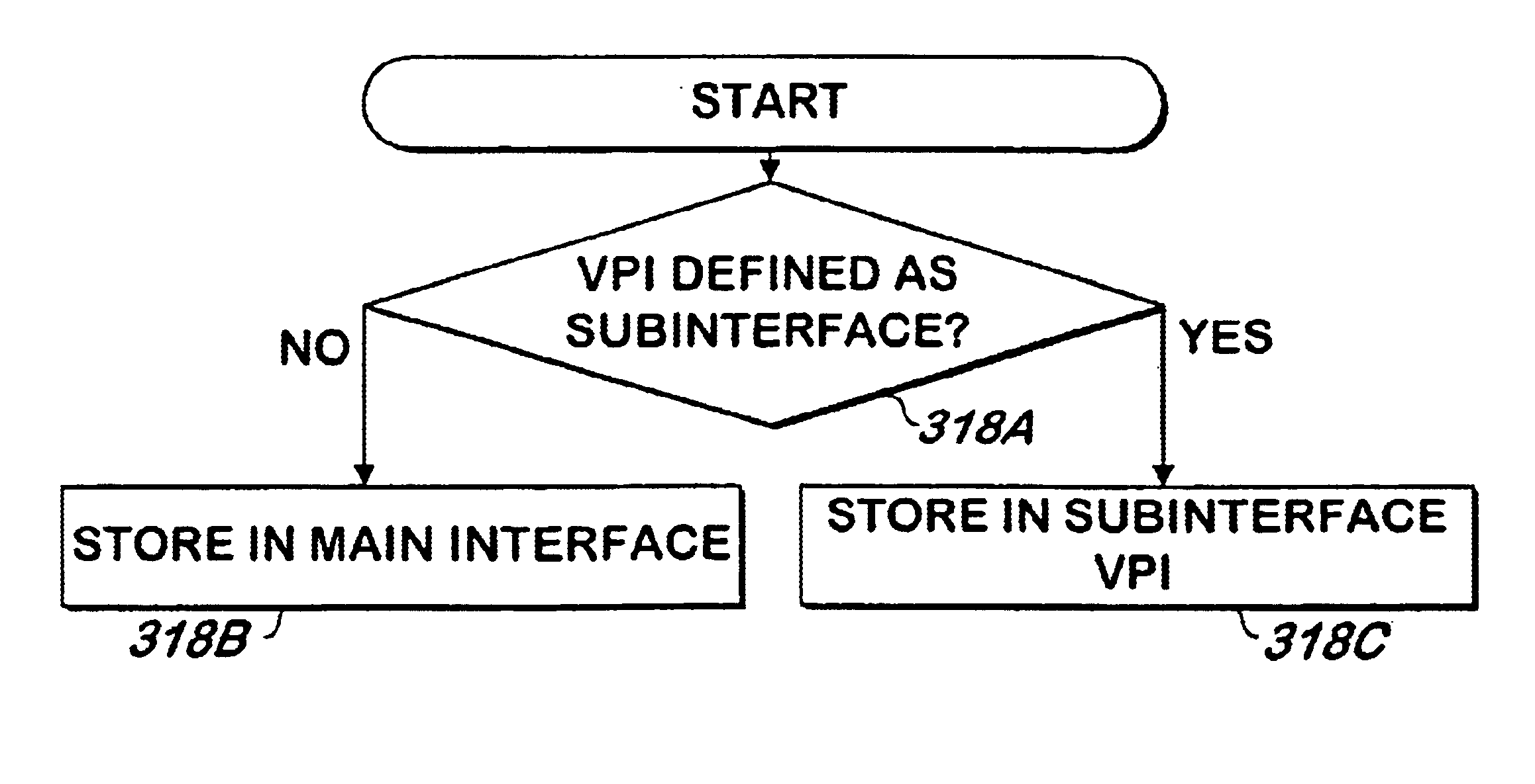
Certain identifiers of the PVC are received from the ATM network device in response to the request made by the endpoint device. One of the identifiers of one or more PVCs may be assigned by the network manager so that it also identifies the subnetwork on the endpoint device to which it is intended to relate. One or more subnetworks may be defined on the endpoint device, with each subnetwork defined using the identifier of the PVC over which the endpoint device will communicate. When the endpoint device requests the configuration information as described above, it receives the identifier of the PVC corresponding to the subnetwork. The endpoint device uses the PVC identifier to associate with the subnetwork the configuration information received for that PVC, avoiding the need for a person to manually associate the configuration information with the proper subnetwork, thereby avoiding errors and saving time.

Problems solved by technology

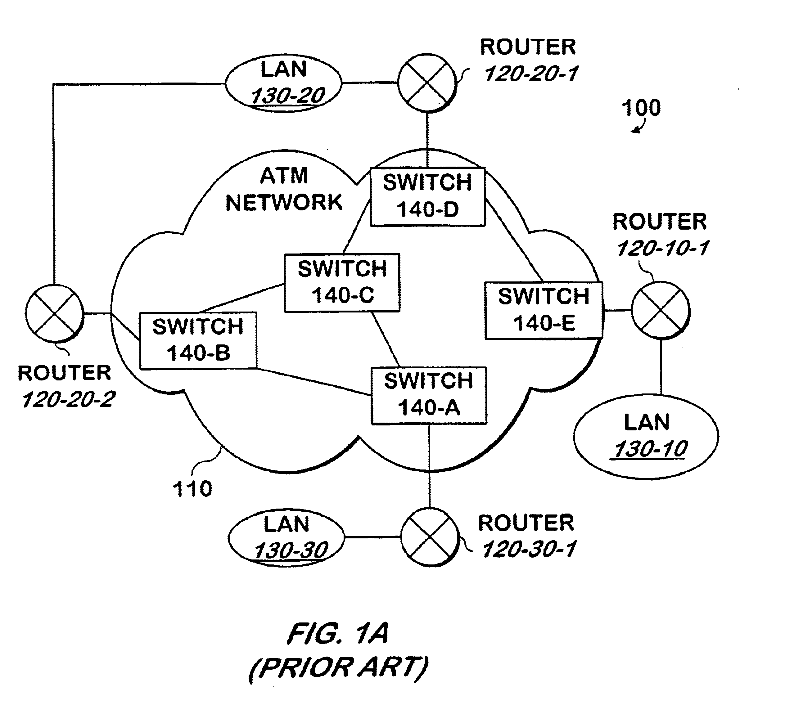
The endpoint devices that will use the PVC 120-30-1, 120-10-1 must also be configured, a tedious, time consuming and error-prone process.
Thus, errors made by the person who configures the endpoint devices can prevent proper communication using the PVC.
Because the person who configures the endpoint device may be different from the person who configures the switches, configuration mismatches are more likely to occur.
If the network manager changes the configuration information in the devices used for the PVC in the ATM network 110, the end point devices 120-30-1, 120-10-1 that use the PVC must also be changed, a tedious, time consuming and error-prone process.
Mistakes that are made in the configuration process may make communication using the PVC impossible or unreliable.
In endpoint devices 120-10-1, 120-20-1, 120-20-2, 120-30-1 that support subinterfaces, the configuration information for each PVC must be properly assigned to the proper main interface or subinterface, a time consuming and error-prone task.
Errors made can cause communication using the PVC to be impossible or unreliable.

Method used


Image

  • Method and apparatus for configuring permanent virtual connection (PVC) information stored on network devices in an ATM network logically configured with subnetworks
  • Method and apparatus for configuring permanent virtual connection (PVC) information stored on network devices in an ATM network logically configured with subnetworks
  • Method and apparatus for configuring permanent virtual connection (PVC) information stored on network devices in an ATM network logically configured with subnetworks

Examples


Embodiment Construction

The present invention may be implemented as computer software in an endpoint device. An endpoint device may be implemented as a conventional computer system.

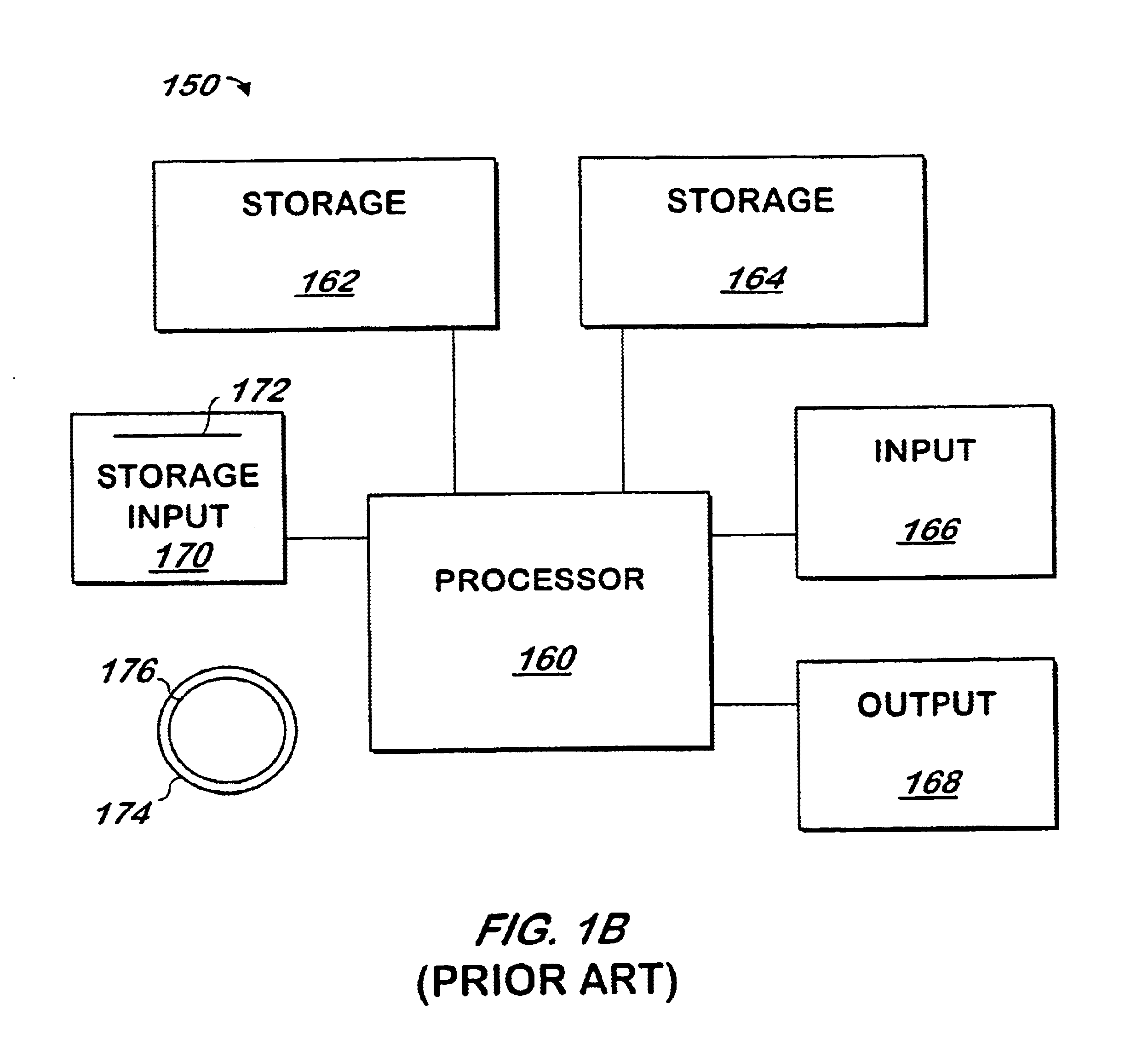
Referring now to FIG. 1B, a conventional computer system 150 for practicing the present invention is shown. Processor 160 retrieves and executes software instructions stored in storage 162 such as memory, which may be Random Access Memory (RAM) and may control other components to perform the present invention. Storage 162 may be used to store program instructions or data or both. Storage 164, such as a computer disk drive or other nonvolatile storage, may provide storage of data or program instructions. In one embodiment, storage 164 provides longer term storage of instructions and data, with storage 162 providing storage for data or instructions that may only be required for a shorter time than that of storage 164. Input device 166 such as a computer keyboard or mouse or both allows user input to the system 150. Output 168, suc...


PUM


Abstract

A method and apparatus retrieves and stores configuration information for network endpoint devices from other devices in the network, such as a switch adjacent to the endpoint device. When the endpoint device establishes a connection with the network, it generates a sequence of SNMP getnext commands using the ILMI interface to obtain the configuration information from the network device. If the network device sends a trap to the endpoint device indicating a change has been made to the configuration parameters stored in the network device for a PVC, a series of SNMP getrequest commands are made using the ILMI interface to retrieve the configuration information for that PVC from the network device. If the endpoint device detects an interruption in communication with the network device, the endpoint device discards the information retrieved previously.

Description

The present invention is related to Asynchronous Transfer Mode (ATM) network software, and more specifically to software configuration of Asynchronous Transfer Mode (ATM) network devices.Communication networks using Asynchronous Transfer Mode technology are known as ATM networks. ATM networks may be used to communicate different types of information to and from many types of devices. The types of information communicated using ATM networks can include computer data, as well as digitized voice or video.Referring now to FIG. 1, a computer network 100 using an ATM network 110 is shown. A set of ATM switches 140A, 140B, 140C, 140D, 140E allows communication between any device, such as a computer coupled to local area networks 130-10, 130-20, 130-30. Each local area network 130-10, 130-20, 130-30 is connected to the set of ATM switches 140A, 140B, 140C, 140D, 140E via one or more routers 120-10-1, 120-20-1, 120-20-2, 120-30-1.Each source of information into the network 110 and recipient ...

Claims


Application Information

Patent Timeline
IPC IPC(8): H04L12/56H04L12/24
CPCH04L12/5601H04L41/0213H04L41/0816H04L41/0853H04L41/0889H04L49/1553H04L41/0856H04L2012/5626H04L41/0895
Inventor LANGLEY, DAVIDLEE, GABRIEL
Owner CISCO TECH INC
Learn More