
Tread stiffening support ribs for runflat tire

a technology of support ribs and runflat tires, which is applied in the direction of wheels, vehicle components, non-skid devices, etc., can solve the problems of uninflated emts, prone to compression of treads, and experience a net compressive load in the sidewall region, so as to prolong the service life and reduce the weight of the vehicle. , the effect of good vehicle runflat handling

Inactive Publication Date: 2004-03-09
THE GOODYEAR TIRE & RUBBER CO
View PDF16 Cites 30 Cited by
  • Summary
  • Abstract
  • Description
  • Claims
  • Application Information

AI Technical Summary

Benefits of technology

Another object of the present invention is to provide a runflat radial tire that is relatively light in weight.
Another object of the present invention is to provide a runflat tire that is able to provide good vehicle runflat handling and an extended runflat service life.
Still another object of the present invention is to provide a runflat tire having a reduced heat generating potential within the tread reinforcing structures during both normal inflated, high-speed operation and especially during runflat operation.
Yet another object of the present invention is to provide a plurality of tread stiffening support that provide puncture protection from cuts and objects picked up on the road.
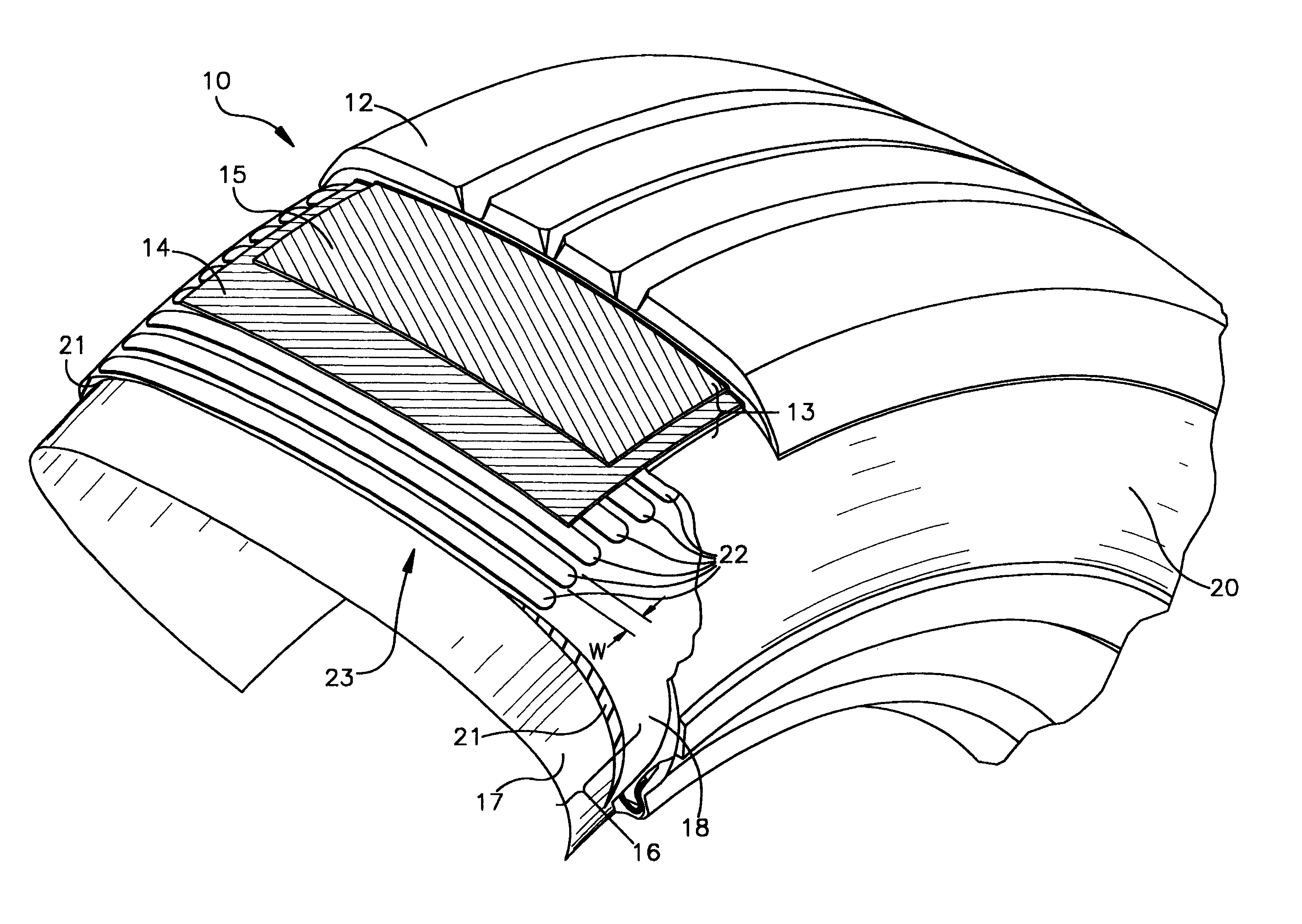
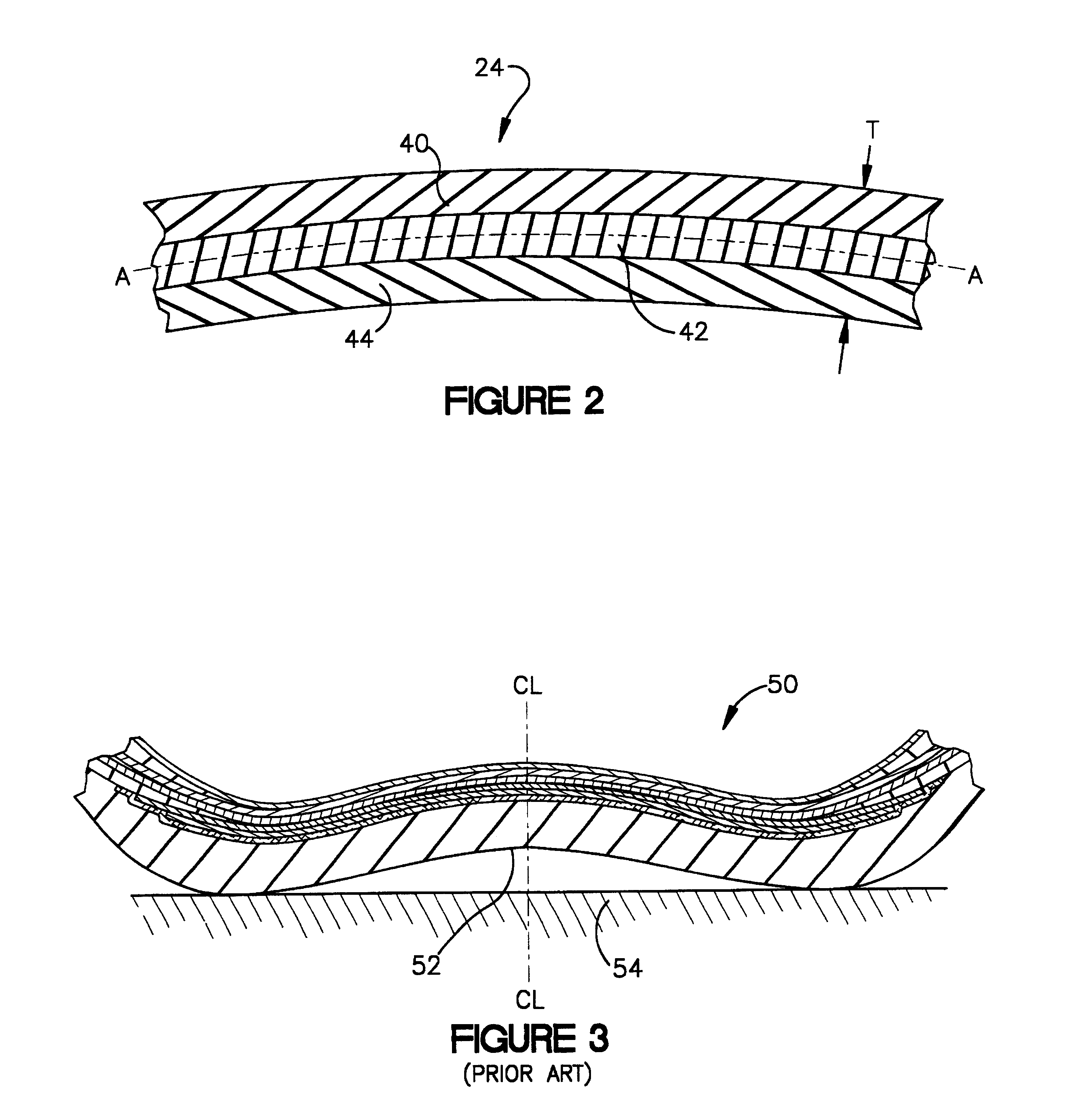
An alternative embodiment incorporates a rib made of three layers of which the first and third layers, i.e., the two outermost layers, are made of a reinforced plastic material as previously described with regard to the first embodiment. The middle layer of the three rib layered rib is made from an elastomeric material, such as urethane or rubber, to allow the ribs to endure shear stresses associated with the tread deflections during normal or runflat operation of the tire.

Problems solved by technology

A conventional pneumatic tire will collapse upon itself, becoming flat, when it is uninflated and carrying the weight of a vehicle.
Such wedge reinforced sidewalls, when operated in the uninflated condition, experience a net compressive load in the region of the sidewall.
The result is that the uninflated EMT tends to have a compressed tread footprint.
More specifically, the transmission of bending forces from the sidewalls to the tread region tend to cause the central portions of the tread to buckle upwards.
The central portion of the tread accordingly tends to lose contact with the ground during runflat operation, having consequent adverse effects upon vehicle handling, especially during high speed operation.

Method used


Image

  • Tread stiffening support ribs for runflat tire
  • Tread stiffening support ribs for runflat tire
  • Tread stiffening support ribs for runflat tire

Examples


Embodiment Construction

FIG. 6 is a meridional cross-sectional view of a runflat tire 100 incorporating a plurality of support members 23 such as parallel-aligned ribs 22 or 24 beneath a tread 102 in the location that is radially inward of the belt structure 104 (shown with a fabric overlay 106) and radially outward of the ply structure 108. (FIG. 6 is essentially a meridional cross-sectional view of a specific tire 100 that is equivalent to the more generalized tire 10 of FIG. 1.) The runflat tire 100 has such additional tire components as the one or more wedge inserts 110a,110b in each sidewall portion 112a,112b, as well as one or more radial carcass plies 114,116, inner liner 118, and bead regions 120a,120b comprising beads 122a,122b and bead apexes 124a,124b.

While the embodiment shown in FIG. 6 (and FIG. 1) is intended to represent a more or less typical runflat tire incorporating the ribs 22 of the present invention (which inhibit lateral and circumferential tread lift during runflat operation), the e...


PUM


Abstract

A pneumatic tire (10) incorporates a plurality of parallel-aligned, tread-stiffening support members (23) typically disposed laterally between the tread (12) and the ply structure (16). The support members (23) inhibit lateral and circumferential tread lift during runflat operation. Support members (23) can each be a monolithic rib (22) made of a fiber reinforced plastic material. An alternative layered rib (24) has two outer layers (40, 44) of a fiber reinforced plastic material while the central layer (42) is an elastomer.

Description

The present invention relates to pneumatic radial-ply runflat tires and in particular to runflat tire construction that reduces lateral and circumferential tread lift during runflat operation.Designers of pneumatic tires have devised various methods by which to make a tire that is capable of providing acceptable performance following sudden, unexpected deflation, such as a tire puncture. Under such conditions, the goal of the tire designer is to design a tire able to provide adequate vehicle handling and safe continued operation over a distance from the place where the tire has lost its pressure to a place desired by the driver, such as a service station where the tire can be repaired or replaced.A pneumatic tire designed for sustained operation under conditions of unpressurization or underpressurization is generally called an extended mobility tire (EMT) or simply a runflat tire. The latter term refers to the tire's ability to be driven while uninflated or in what would generally b...

Claims


Application Information

Patent Timeline
IPC IPC(8): B60C9/18B60C17/00
CPCB60C9/18B60C17/00Y10T152/10765Y10T152/10171
Inventor ABBOTT, JOHN RONALD
Owner THE GOODYEAR TIRE & RUBBER CO
Learn More