

Pulp moulding process and related system
- Summary
- Abstract
- Description
- Claims
- Application Information
AI Technical Summary
Benefits of technology
Problems solved by technology
Method used
Image

Examples
Embodiment Construction
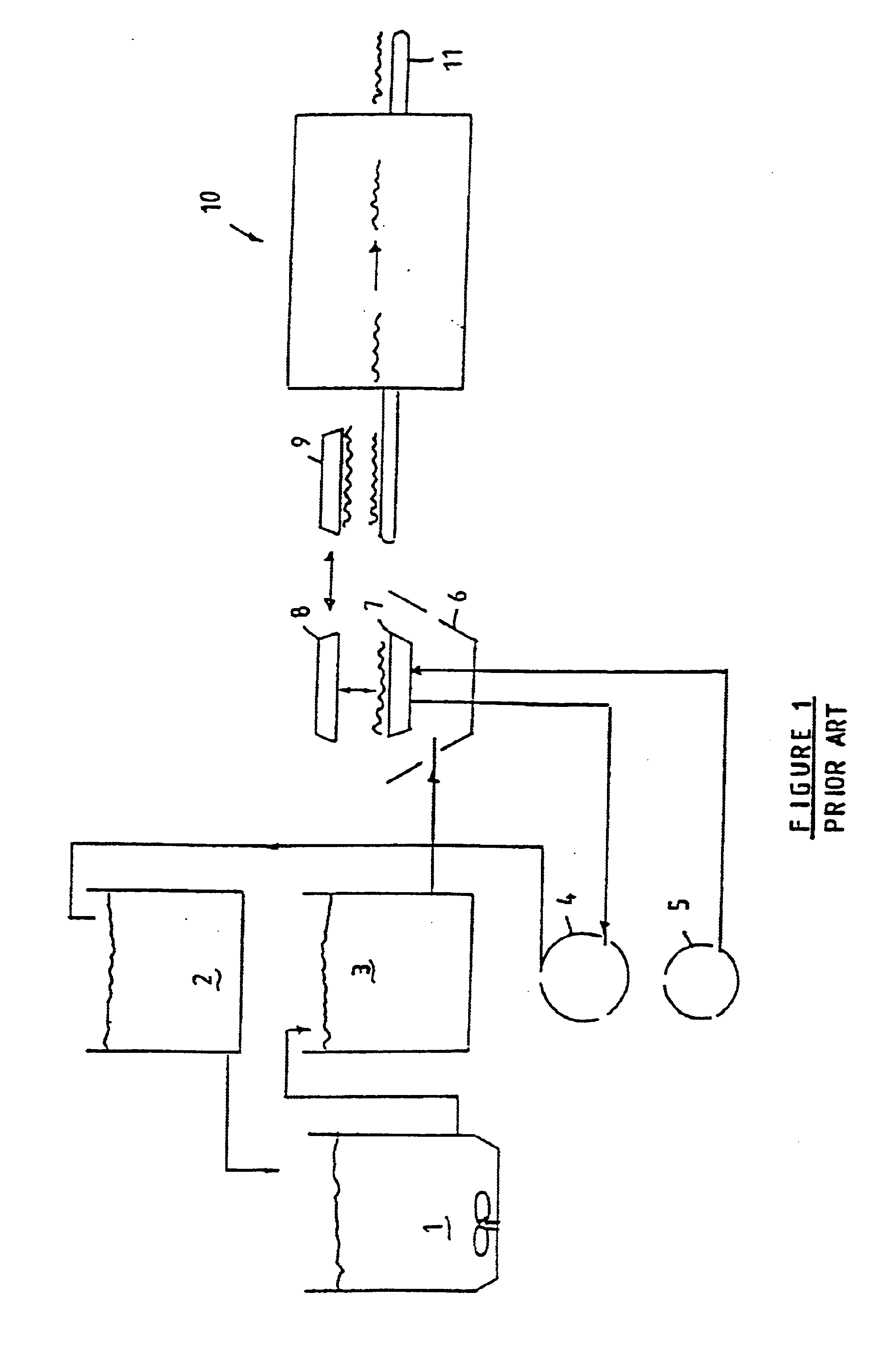
A traditional pulp moulding process as illustrated in FIG. 1 typically includes a pulper (1) in which weighed raw materials such as waste paper is loaded together with processed water from a white water feed tank (2) in the required dry fibre-to-water ratio and pulped. Once the required pulp is obtained, it is pumped to a stock container (3) from where it is fed on demand to a moulder (6).
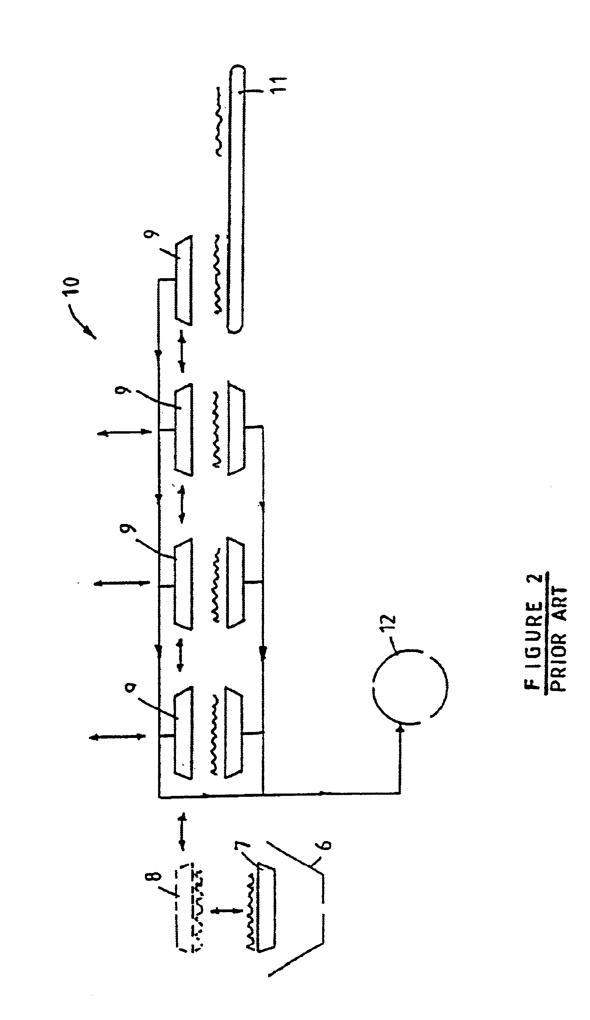
The moulder (6) includes a set of forming dies (7), consisting of perforated bases over which fine mesh is fitted. During the process, vacuum is applied to the forming dies (7) or moulds while they are submerged in the pulp. During this forming process, water in the solution is drawn through the mesh, leaving behind matted fibres in the shape of the product as formed by the forming dies (7). The forming dies (7) are then removed from the pulp and engaged with transfer dies (8) or moulds. Vacuum is then applied to the transfer dies (8) while positive pressure is simultaneously applied to the forming...
PUM
| Property | Measurement | Unit |
|---|---|---|
| Fraction | aaaaa | aaaaa |
| Pressure | aaaaa | aaaaa |
| Flow rate | aaaaa | aaaaa |
Abstract
Description
Claims
Application Information