System for vibration in a centrifuge

a centrifuge and vibration technology, applied in centrifuges, filtration separation, separation processes, etc., to achieve the effect of reducing the friction effect of the receptacle wall, preventing or reducing the compacting of more dense materials

Inactive Publication Date: 2004-03-16
PHASE
View PDF64 Cites 24 Cited by
  • Summary
  • Abstract
  • Description
  • Claims
  • Application Information

AI Technical Summary

Benefits of technology

One technical advantage of the present invention may include reducing friction effect of a receptacle wall with respect to movement of more dense material along the wall. Vibration in the receptacle may create a "slippery" wall effect thus reducing effective frictional forces imparted on more dense material against the walls. This "slippery" wall effect may cause more dense material to proceed along the wall to an associated opening for separation from a fluid medium.
Another technical advantage of the present invention includes preventing or reducing compacting of more dense material in a receptacle during increased de-watering. Vibration may cause more dense material to collect in the receptacle and move through an associated opening. A build up of such more dense material may clog the opening further compacting more dense material, which removes more clarified fluid. Vibrations may then cause the particle to breakup at a desired operating condition thus removing the de-watered more dense material from the receptacle.
A further technical advantage of the present invention may include varying the velocity of separation of more dense material in a fluid medium. Steep or shallow walls on an

Problems solved by technology

This "slippery" wall effect may cause more dense material to proceed alo

Method used


Image

  • System for vibration in a centrifuge
  • System for vibration in a centrifuge
  • System for vibration in a centrifuge

Examples


Embodiment Construction

Preferred embodiments of the present invention and their advantages are best understood by reference to FIGS. 1 through 11D where like numbers are used to indicate like and corresponding parts.

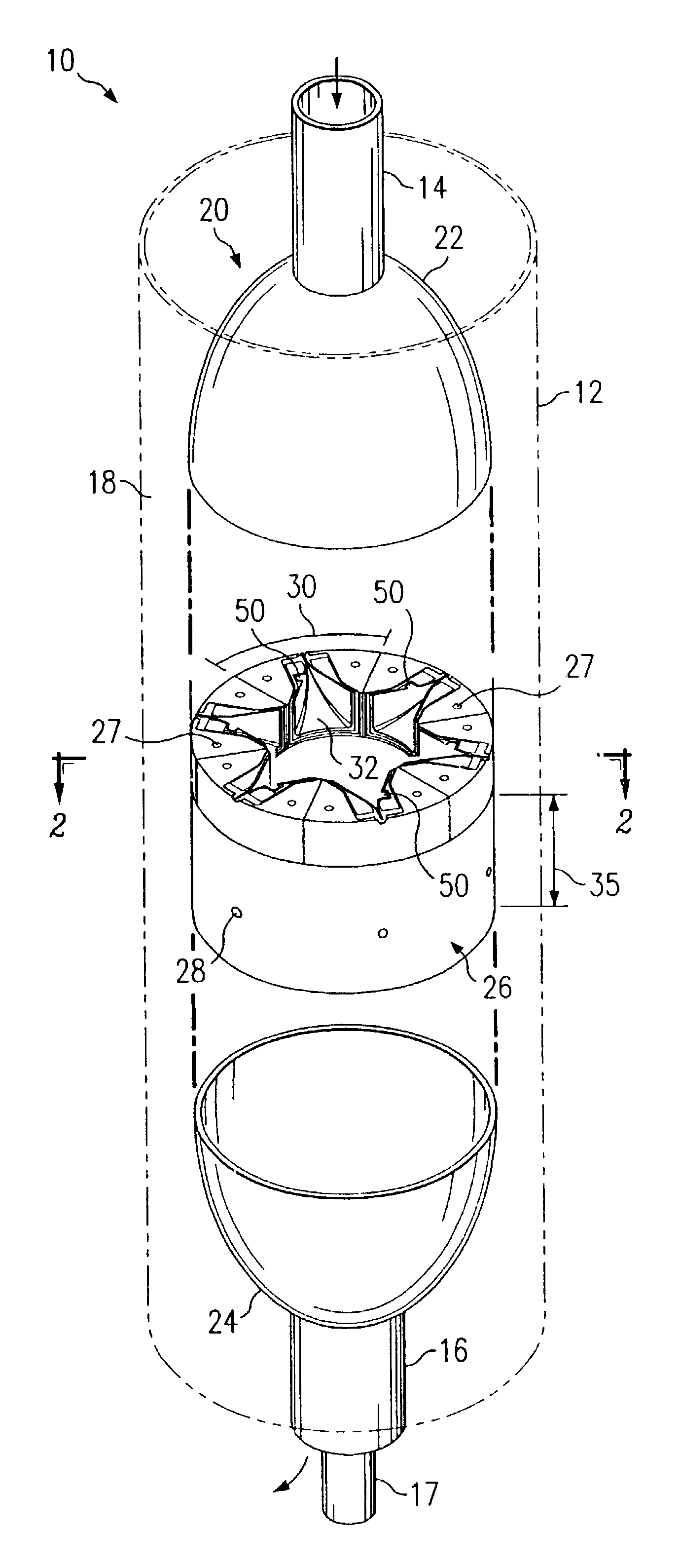
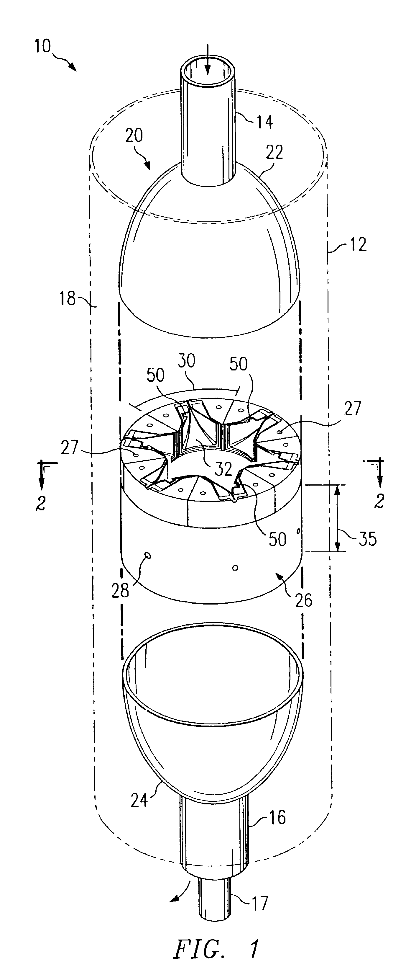
FIG. 1 illustrates a schematic drawing showing an isometric view with portions broken away of centrifuge 10. Centrifuge 10 may include centrifugal core 20 disposed within non-rotating outer sleeve 12. Centrifugal core 20 may include fluid medium inlet 14, clarified fluid outlet 16, and fluid separation wall 26. Fluid separation wall 26 may be encapsulated between first housing cover 22 and second housing cover 24.

Non-rotating outer sleeve 12 may form accumulation area or containment zone 18 between centrifugal core 20 and non-rotating outer sleeve 12. Accumulation area 18 may collect more dense material and other contaminants that have been separated from the fluid medium and have passed through openings 28. More dense material and other contaminants that have collected within accumulation are...


PUM

PropertyMeasurementUnit
Poweraaaaaaaaaa
Poweraaaaaaaaaa
Frequencyaaaaaaaaaa

Abstract

A system and method for vibration in a centrifuge is disclosed. A centrifuge for removing more dense material from a fluid medium includes a fluid separation wall placed within a non-rotating sleeve. The fluid separation wall rotates around the axis of rotation and includes an inner surface and an outer surface with at least one receptacle formed on the inner surface of the fluid separation wall. The receptacle aids in separation of more dense material from the fluid medium by forming a void space between the inner and outer surface. An excitation apparatus associated with the receptacle to create a vibration within the receptacle. A flow path may extend through the wall from the void area to the outer surface to transport more dense material to the containment zone.

Description

TECHNICAL FIELD OF THE INVENTIONThis disclosure relates in general to the field of centrifugal separators, and more particularly to a system and method for vibration in a centrifuge.BACKGROUND OF THE INVENTIONThe demand for efficient removal of contaminants from water supplies has increased. Because of their relatively small size, many light density contaminants (e.g., microorganisms) may often not be removed by conventional processing methods including fluid separation.Fluid separation may include any process that captures and removes materials from a liquid stream, typically resulting in a clarified liquid having reduced contaminants and a denser stream containing removed contaminants. Further treating the denser stream in a thickening process may remove additional liquid to leave a thick, pump-able slurry mixture containing nine percent to approximately twelve percent solids by weight. Under certain conditions, a de-watering process may remove more water from the slurry mixture. ...

Claims


Application Information

Patent Timeline
IPC IPC(8): B04B1/10B04B11/00B04B7/00B04B7/08B04B1/00B01D33/44B01D33/54B01D17/038
CPCB04B1/00B04B1/10B04B7/08B04B11/00B01D33/54
Inventor KIRKER, CURTISFULLER, BERKELEY F.
Owner PHASE
Why Eureka
Try Eureka