Laser optical bench for laser desorption ion sources and method of use thereof

a laser and optical bench technology, applied in the field of laser desorption ion sources, can solve the problems of increasing the laser radiant power, requiring concomitant laser radiation power, and still observing statistically significant perturbations,

Inactive Publication Date: 2004-03-16
CIPHERGEN BIOSYSTEMS INC
View PDF9 Cites 13 Cited by
  • Summary
  • Abstract
  • Description
  • Claims
  • Application Information

AI Technical Summary

Problems solved by technology

Although some approaches, such as SELDI, function to minimize these effects, statistically significant perturbations may still be observed.
Consequently, a given increase in laser spot area would require a concomitant increase in laser radiant power.

Method used


Image

  • Laser optical bench for laser desorption ion sources and method of use thereof
  • Laser optical bench for laser desorption ion sources and method of use thereof
  • Laser optical bench for laser desorption ion sources and method of use thereof

Examples


Embodiment Construction

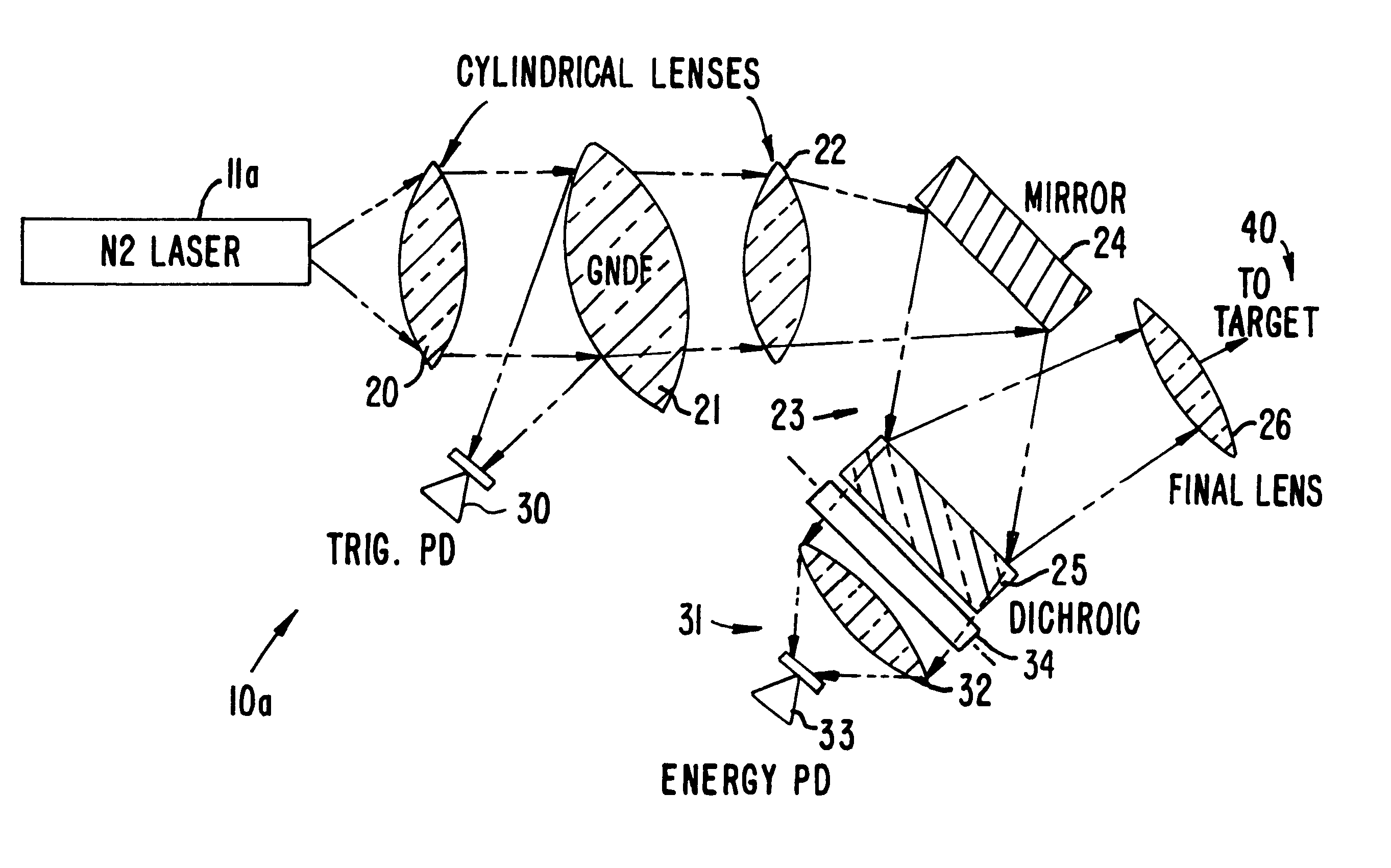
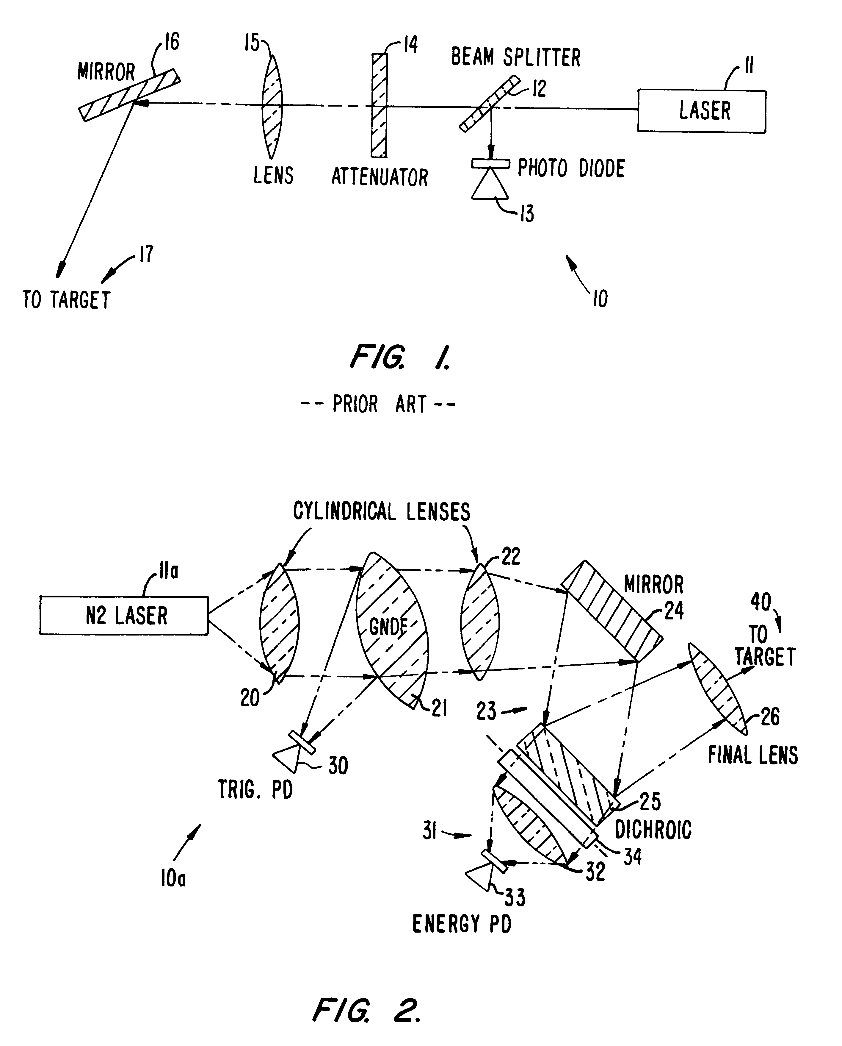
With reference to FIG. 2, a laser optical bench 10a in accordance with a preferred embodiment of the present invention is illustrated. The laser optical bench includes a light source or photon source 11a, preferably in the form of a laser. A first lens is provided for focusing light from the laser onto an attenuator 21. A second lens 22 is provided as a focusing element for focusing light from the attenuator to a beam steering apparatus. Preferably, the beam steering apparatus includes a mirror 24 and a filter 25. In preferred embodiments, the filter consists of a dichroic filter or a dichroic mirror. Finally, a final lens 26 is provided as a focusing element for focusing light on a target 40, which is generally a sample probe.

In preferred embodiments, a trigger photodetector or photodiode 30 is provided as a lasing event sensor. Trigger photodiode 30 receives light from attenuator 21 and thus, attenuator 21 also serves as a beam splitter in such an embodiment.

Additionally, in prefe...


PUM


Abstract

A laser optical bench for use with a laser desorption/ionization mass spectrometer. The laser optical bench includes a laser for producing light, a focusing structure that receives light from the laser and focuses predominantly in a single plane, an attenuator that receives light from the focusing structure, beam steering structure for directing light from the attenuator from the target; and a final focusing element for focusing light from the beam steering structure on the target. Further focusing elements may be included for further focusing and dispersing the light beam in different planes. Additionally, photodetectors or photodiodes may be included for energy measurement and sensing a lasing event.

Description

1. Field of the InventionThe present invention relates to a laser desorption ion source, and more particularly, to a laser optical bench for use with a laser desorption ion source that preferentially shapes a beam from a light source by predominantly focusing the beam in a single plane.2. Description of the Prior ArtA laser desorption ion source is a device that utilizes the energy inherent in a focused laser beam to promote the desorption of neutrals and / or ions from solid or liquid state matter. In the case of solid matter, materials or samples of interest are presented as solid state crystals or thin films upon a sample support typically referred to as a probe. For liquid matter, the fluids are introduced as droplets or a fine spray and may be desorbed in stream or upon a physical support.The energy transfer process may proceed through direct thermal or electronic excitation of the material or through indirect thermal excitation. If the material directly absorbs energy from the l...

Claims


Application Information

Patent Timeline
IPC IPC(8): H01J49/10H01J49/16G01N27/62
CPCH01J49/164
Inventor WEINBERGER, SCOT R.BRYAN, RAYMOND G.
Owner CIPHERGEN BIOSYSTEMS INC
Why Eureka
Try Eureka