
Bale processor

Inactive Publication Date: 2004-03-23
HIGHLINE MFG INC
View PDF52 Cites 14 Cited by
  • Summary
  • Abstract
  • Description
  • Claims
  • Application Information

AI Technical Summary

Benefits of technology

It is an object of the present invention to provide a bale processor having operational flexibility and enhanced durability. According to a broad aspect of the invention, the invention provides an apparatus for processing baled crop material comprising: a chassis having a front and back end and a left and right side; a processing tub having two opposing end walls, two opposing side walls and a discharge opening located in one of the side walls; a disintegrator mounted in the processing tub adapted to disintegrate baled crop material positioned within the tub and discharge the processed bale material out the discharge opening; and a manipulator mounted within the processing tub adapted to manipulate the baled crop material to expose different parts thereof to the disintegrator; wherein the processing tub is adapted to be mounted on the chassis such that the discharge opening can be positioned on either the left or right side of the chassis.
The invention provides an improved bale processor that is easily convertible from a left-hand discharge arrangement to a right-hand discharge arrangement. Furthermore, the bale processor can process a large square bale or, alternatively, one or more round bales and includes an adjustable bale loading mechanism for loading bales of different configurations. Moreover, the bale processor includes a hydraulic selector assembly such that a single set of hydraulic lines can be used to operate two separate hydraulic systems on the bale processor.

Problems solved by technology

However, primarily due to the large size and weight of modern "square" bales (which have a rectangular configuration), problems may be encountered with operational flexibility and durability of some processors.
Moreover, some known processors are not adapted for easy use with older tractors due to hydraulic feed line requirements exceeding the typical number of hydraulic ports on such tractors.

Method used


Image

  • Bale processor
  • Bale processor
  • Bale processor

Examples


Embodiment Construction

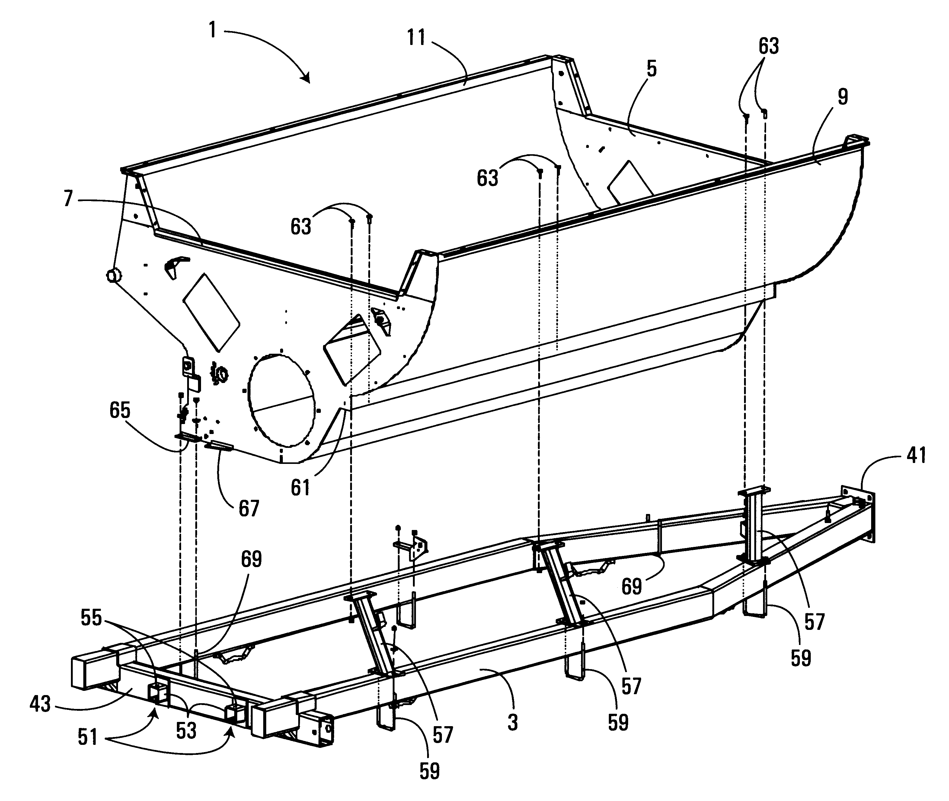
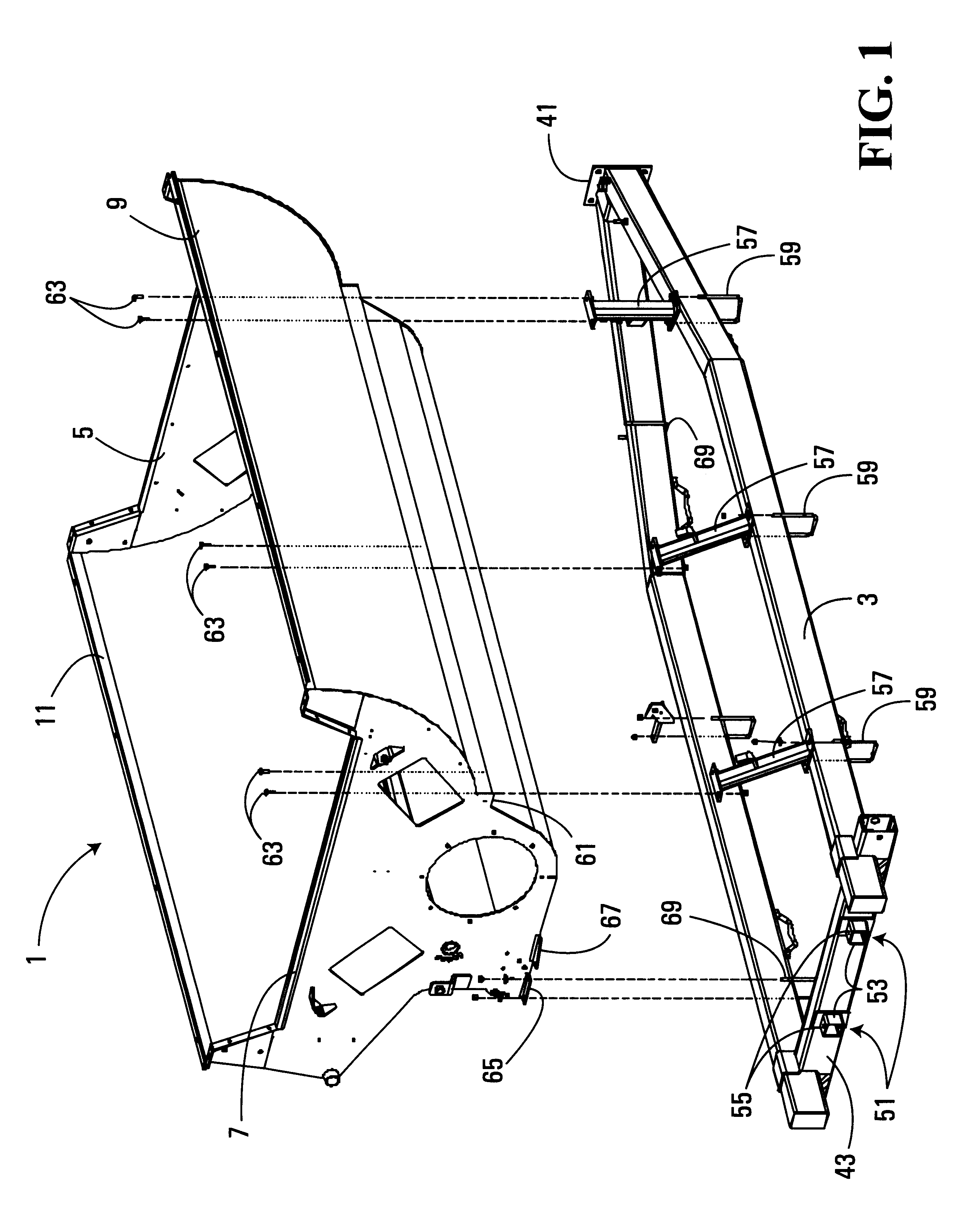
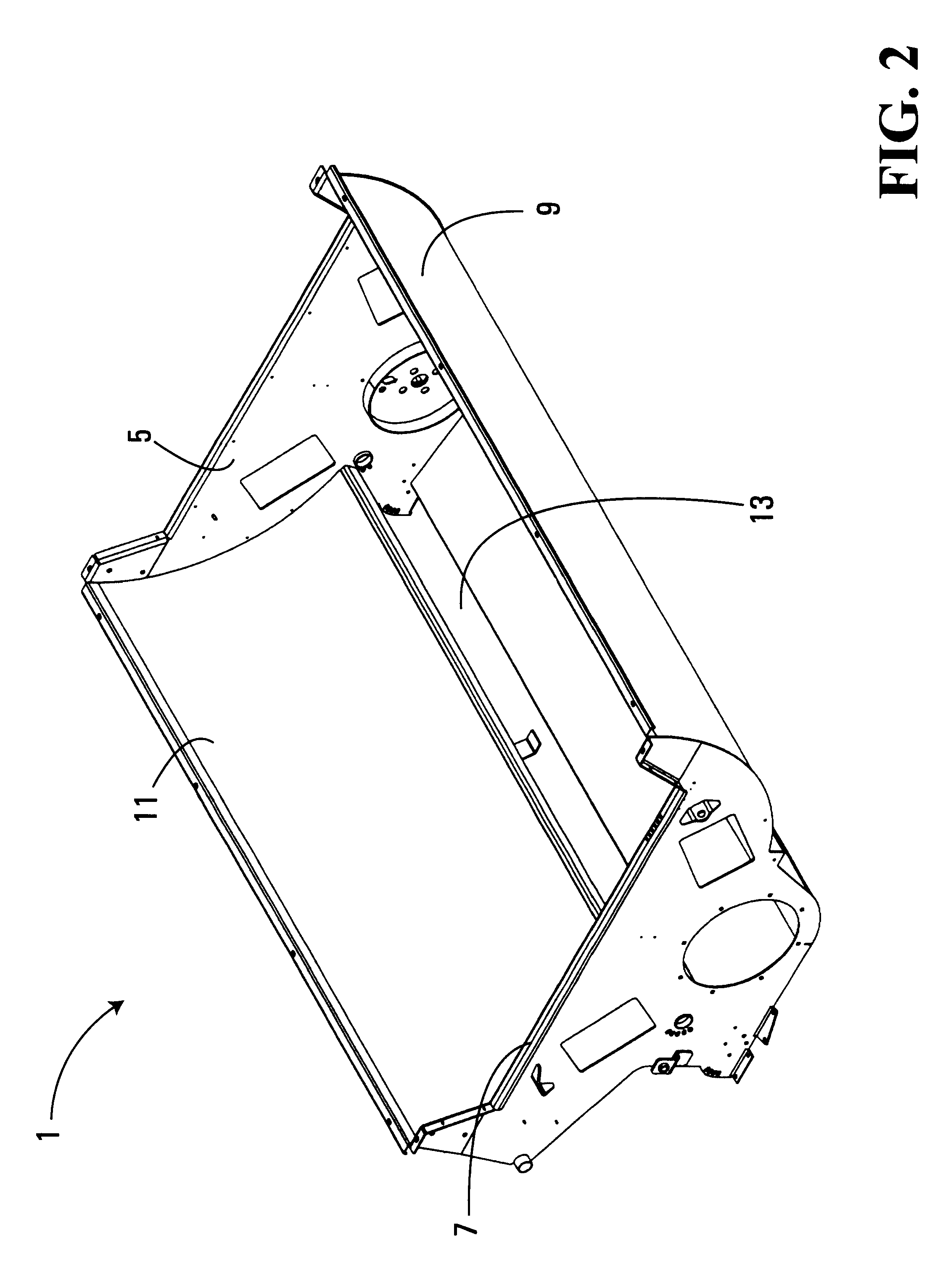
As shown in FIGS. 1 and 2, the bale processor comprises a processing tub 1 mounted on a chassis 3. The tub 1 has end walls 5 and 7 and side walls 9 and 11. A discharge opening 13 is provided at the bottom of side wall 11. In the embodiment shown in FIGS. 1 and 14, side wall 11 is located on the left-hand side of the bale processor. As discussed below, the processing tub 1 and the chassis 3 are designed such that the processing tub can be rotated 180 degrees to position side wall 11 on the right-hand side of the apparatus (see FIGS. 6 and 15).

The processing tub 1 is sized such that a large square bale may be positioned lengthwise therein for processing. Typically, an inside width of approximately 7.5 feet (side wall 9 to side wall 11) and an inside length of at least 10 feet (from end wall 5 to end wall 7) is sufficient to accommodate most large bales. A tub of these dimensions can also accommodate two or more round bales lengthwise therein for processing at the same time.

As shown in...


PUM


Abstract

Disclosed is an apparatus for disintegrating bales of agricultural material such as hay. The apparatus has a a chassis, a processing tub with a discharge opening located in one of its side walls, a disintegrator mounted in the processing tub to disintegrate baled crop material positioned within the tub and discharge the processed bale material out the discharge opening and a manipulator mounted within the processing tub adapted to manipulate the baled crop material to expose different parts thereof to the disintegrator. The processing tub is adapted to be mounted on the chassis such that the discharge opening can be positioned on either the left or right side of the chassis. In an embodiment of the invention, the processing tub is sized to accommodated a large square bale lengthwise therein or two or more round bales. The apparatus is also provided with an adjustable fork lift to raise bales of different configurations into the processing tube and a hydraulic selector valve such that two sets of hydraulic systems on the processor can be operated by a single hydraulic line from a tractor or other power source.

Description

FIELD OF INVENTIONThe invention relates to an improved apparatus for disintegrating bales of agricultural material such as hay.BACKGROUNDBale processors, including processors of the type having a tub with longitudinally disposed disintegration flail rollers and bale support rollers (as disclosed in Canadian Patent No. 2,086,569 owned by the applicant herein) are known. However, primarily due to the large size and weight of modern "square" bales (which have a rectangular configuration), problems may be encountered with operational flexibility and durability of some processors. Further, the majority of the processors known to the inventors are only adapted to process one type of common form of bale (i.e. "round" or "square") and are only adapted to discharge out of one side of the processor. Moreover, some known processors are not adapted for easy use with older tractors due to hydraulic feed line requirements exceeding the typical number of hydraulic ports on such tractors.SUMMARY OF...

Claims


Application Information

Patent Timeline
IPC IPC(8): A01D87/00A01D87/12A01F29/00
CPCA01D87/122A01D87/127A01F29/005A01D2087/128Y10S241/605
Inventor PATTERSON, DAVIDKOSOKOWSKY, MURRAYLISCHYNSKI, KIMBALLLEPAGE, CHARLES
Owner HIGHLINE MFG INC
Learn More