Custom replacement device for resurfacing a femur and method of making the same

a replacement device and femur technology, applied in the field of knee joint replacement devices, can solve the problems of degenerative arthritis, tracking problems, and patella dislocation or slippage, and achieve the effects of improving the quality of li

Inactive Publication Date: 2004-03-30
KINAMED
View PDF12 Cites 601 Cited by
  • Summary
  • Abstract
  • Description
  • Claims
  • Application Information

AI Technical Summary

Problems solved by technology

For example, the patella may dislocate or slip out of place, it may fracture, or develop a tracking problem.
A tracking problem occurs when the patella no longer remains centered within the groove as it glides over the femur.
The resulting abnormal biomechanics can cause chronic pain in the joint and if left untreated, it can lead to degenerative arthritis.
When this cartilage breaks down, the cushion is lost, resulting in pain, swelling, bone spur formation and/or decreased range of motion of the knee joint.
Due to the inability of damaged cartilage to repair itself after injury, the range of treatment for patients with unicompartmental disease involving the patella is limited.
In certain instances none of these

Method used


Image

  • Custom replacement device for resurfacing a femur and method of making the same
  • Custom replacement device for resurfacing a femur and method of making the same
  • Custom replacement device for resurfacing a femur and method of making the same

Examples


Embodiment Construction

is discussed below.

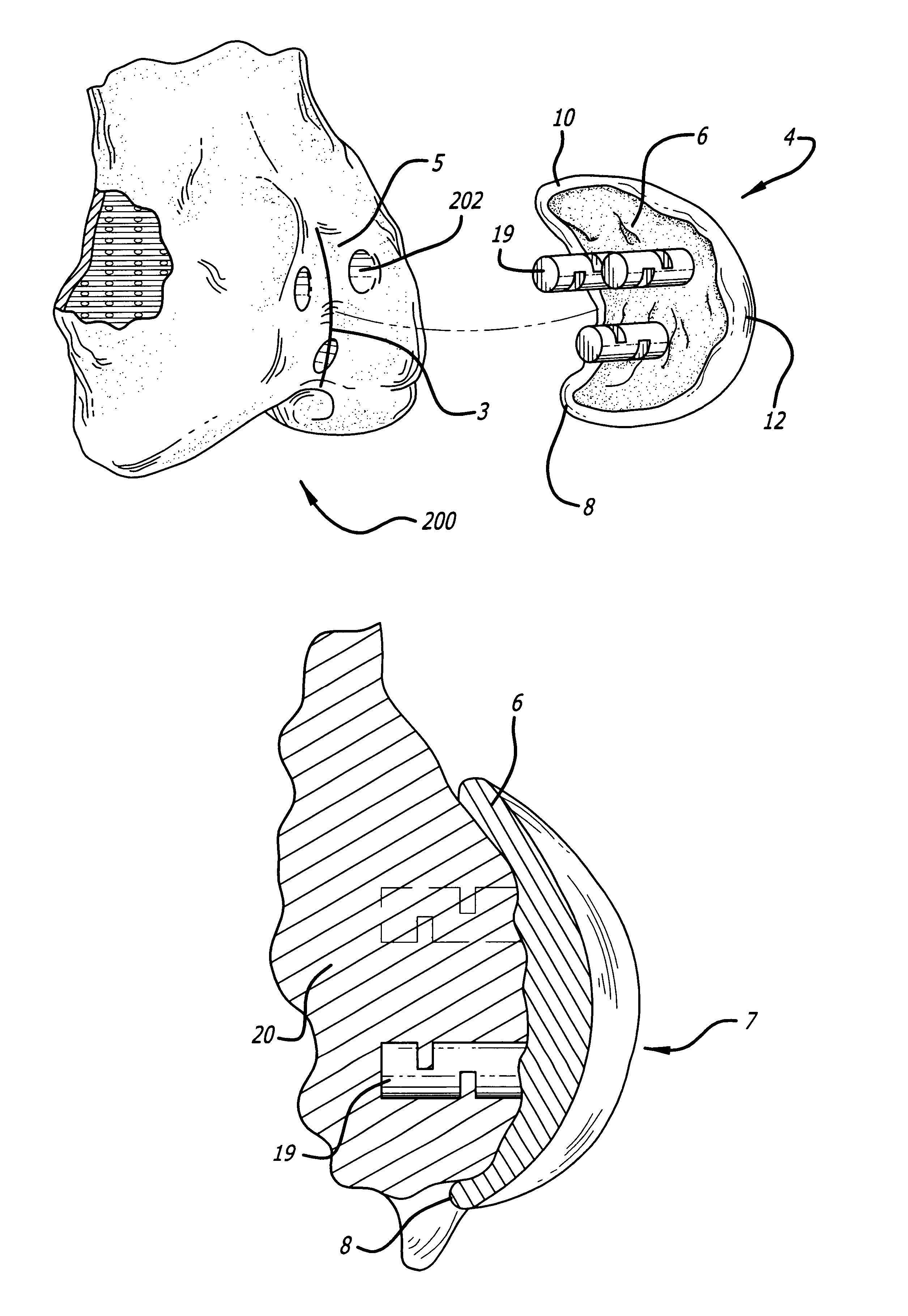
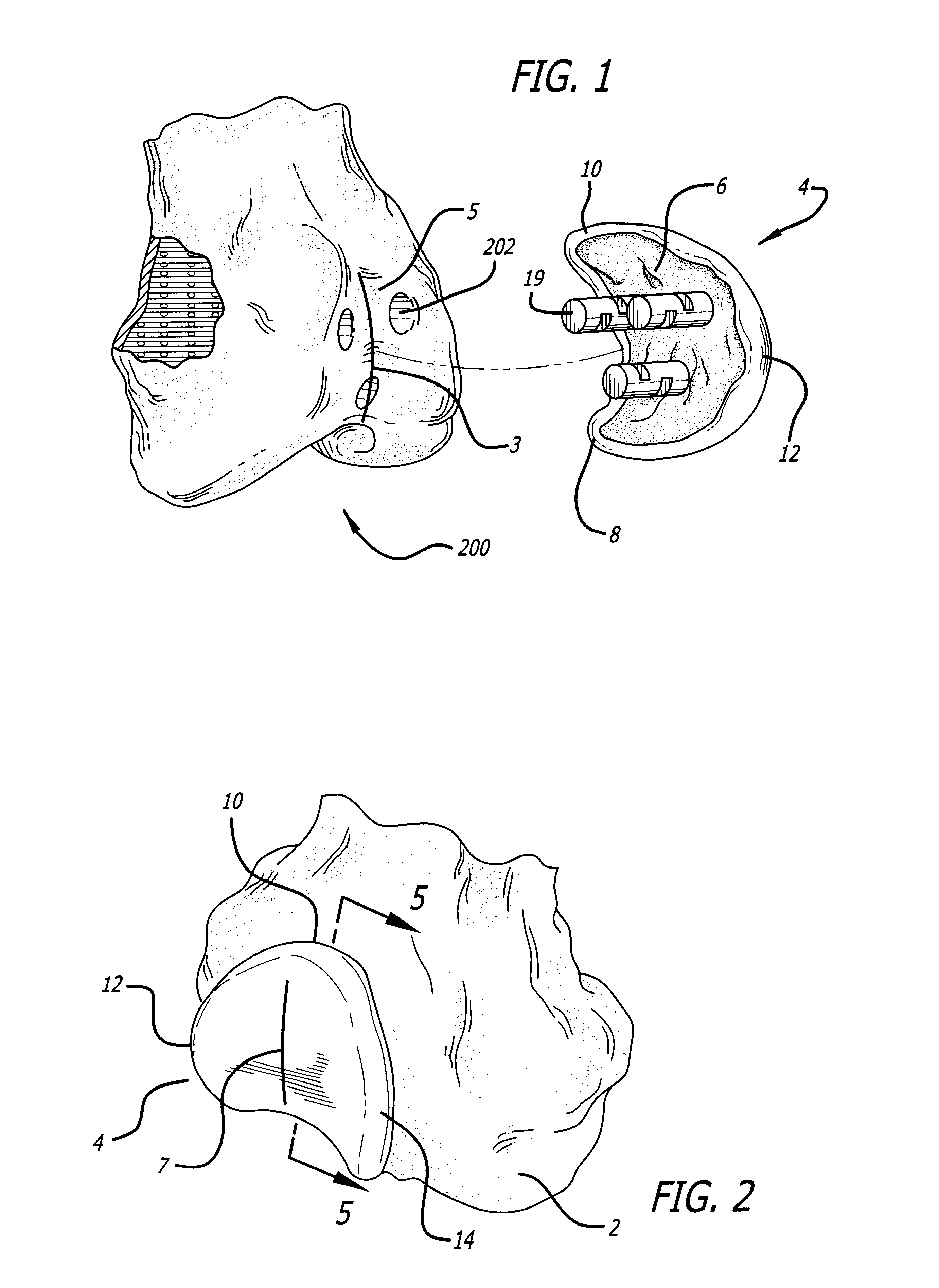
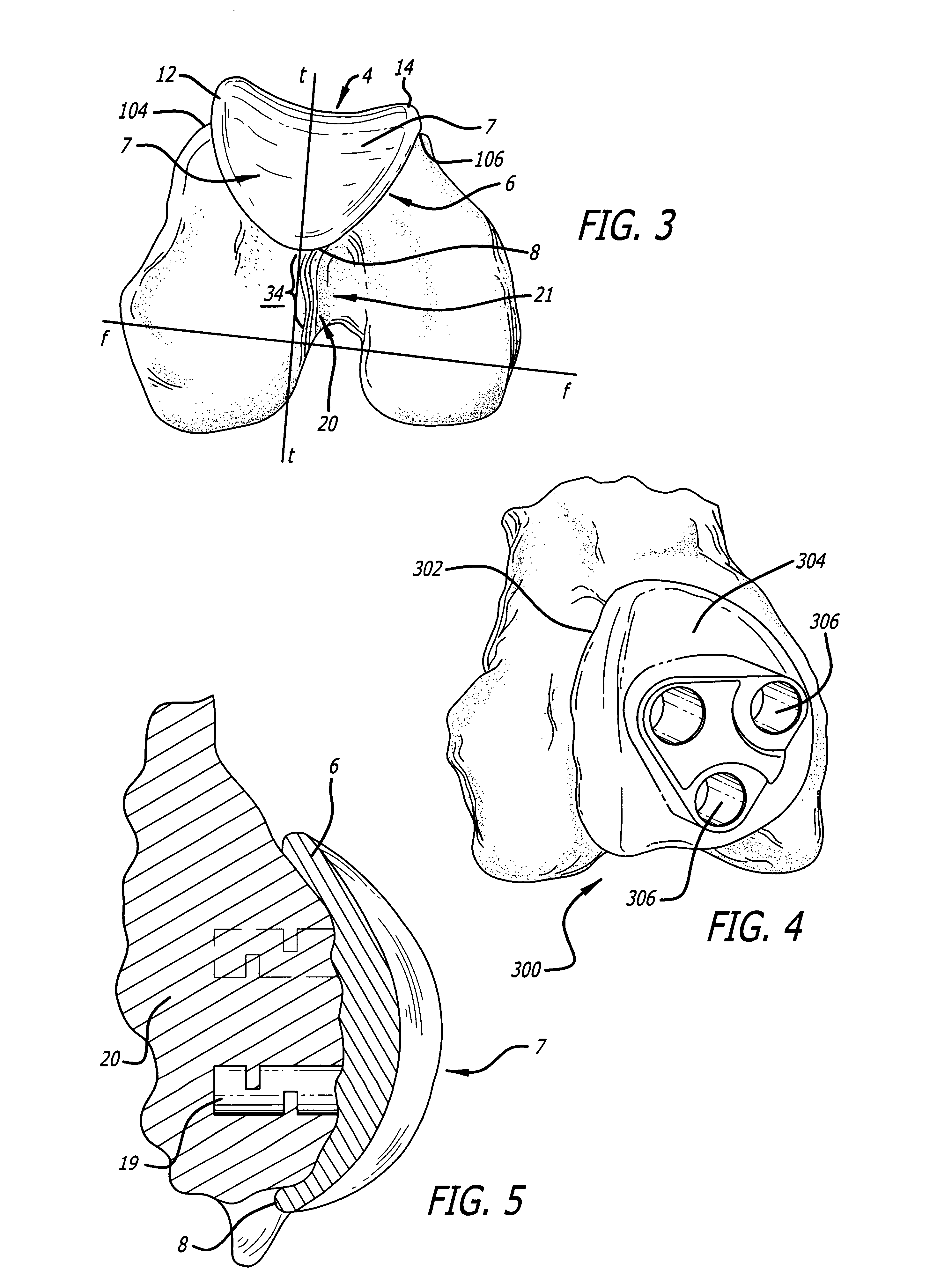
As illustrated by way of example in FIGS. 2 and 9, one embodiment of the present invention includes a custom replacement device 4 adapted to associate with the distal end of a patient's femur 2. FIG. 2 shows a model made of the patient's femur in FIG. 9. The model 200 is substantially similar to the patient's femur 2 and is used to make the custom replacement device 4 (as discussed below). The surface near the distal end of the femur 2 defines a patellar face 5, and along the patellar face is a trochlear groove 3 of the femur. FIGS. 7 and 8 show exemplary views of a normal, intact knee joint. Referring to FIG. 8, on a healthy knee, the trochlear groove would be covered with about 5 mm of articular cartilage 100. However, if the articular cartilage wears down for any reason, the cushion and sliding surface that the cartilage provides is lost, resulting in pain, and therefore may need to be replaced with the custom replacement device 4.

One of the advantages with the...


PUM

PropertyMeasurementUnit
Lengthaaaaaaaaaa
Lengthaaaaaaaaaa
Lengthaaaaaaaaaa

Abstract

A replacement device for resurfacing a joint surface of a femur and a method of making and installing such a device is provided. The custom replacement device is designed to substantially fit the trochlear groove surface, of an individual femur. Thereby creating a "customized" replacement device for that individual femur and maintaining the original kinematics of the joint. The replacement device may be defined by four boundary points, and a first and a second surface. The first of four points is 3 to 5 mm from the point of attachment of the anterior cruciate ligament to the femur. The second point is near the bottom edge of the end of the natural articulatar cartilage. The third point is at the top ridge of the right condyle and the fourth point at the top ridge of the left condyle of the femur. The top surface is designed so as to maintain centrally directed tracking of the patella perpendicular to the plane established by the distal end of the femoral condyles and aligned with the center of the femoral head.

Description

1. Field of InventionThe invention relates generally to a replacement device for a knee joint, and more particularly, to a device for resurfacing the trochlear groove of a femur that is customized to an individual and to methods for installing and making the same.2. Description of the Related ArtThe human knee joint primarily includes three parts, anatomically referred to as the femur (thighbone), the tibia (shinbone) and the patella (kneecap). The knee joint is then further subdivided into two joints: the patella-femoral joint (space between the kneecap and distal anterior surface of the thighbone) and the tibia-femoral (space between the thighbone and shinbone).During normal bending and straightening of the leg, the patella (kneecap) slides over the femur (thighbone) within a groove that is located on the front distal surface of the femur. This groove is referred to as the trochlear groove. Several types of abnormalities can occur with the movement of the patella over the femur. F...

Claims


Application Information

Patent Timeline
IPC IPC(8): A61B17/16A61B17/17A61F2/30A61F2/38A61F2/00A61B17/00
CPCA61F2/30942A61F2/3877A61F2/3859A61F2/461A61B17/1764A61B17/00491Y10T29/49764A61F2/30767A61F2002/30125A61F2002/30594A61F2002/30685A61F2002/30892A61F2002/30948A61F2002/30952A61F2002/30957A61F2230/0008A61F2310/00017A61F2310/00023A61F2310/00029A61F2310/00203A61F2310/00239A61F2310/00407A61F2310/00796Y10S623/901A61B34/10A61B2034/108A61F2/4657A61F2002/4658
Inventor CARIGNAN, ROGERPRATT, CLYDE R.
Owner KINAMED
Why Eureka
Try Eureka