Method and software-implemented apparatus for ground plane estimation in multi-dimensional data

a multi-dimensional imagery and ground plane technology, applied in image enhancement, image analysis, indoor games, etc., can solve the problems of erroneous feature extraction, inaccurate determination of the object-to-ground interface, and erroneous object segmentation

Inactive Publication Date: 2004-03-30
LOCKHEED MARTIN CORP
View PDF13 Cites 10 Cited by
  • Summary
  • Abstract
  • Description
  • Claims
  • Application Information

AI Technical Summary

Problems solved by technology

A significant problem with prior art ground plane estimation methods is inaccurate determination of the object-to-ground interface.
This problem can lead to erroneous object segmentation, erroneous feature extraction, erroneous feature comparisons, and ultimately to incorrect or missed object identifications.
However, utilization of traditional ground plane estimation methods would lead to intolerable directional errors in the estimated ground plane.
However, several new problems are introduced by the illustrative detector, over and above the problems with traditional detectors.
Complex terrain exacerbates the inaccurate ground / object interface problem.
The problems associated with that method were exacerbated for objects in complex terrain where multiple "ground planes" or surfaces may exist.
Those multiple surfaces in combination with one, and commonly several, unknown objects make it extremely difficult to extract an optimal ground plane estimate for each and every detected object.
Yet another problem with prior art detection methods is processor over usage.

Method used


Image

  • Method and software-implemented apparatus for ground plane estimation in multi-dimensional data
  • Method and software-implemented apparatus for ground plane estimation in multi-dimensional data
  • Method and software-implemented apparatus for ground plane estimation in multi-dimensional data

Examples


Embodiment Construction

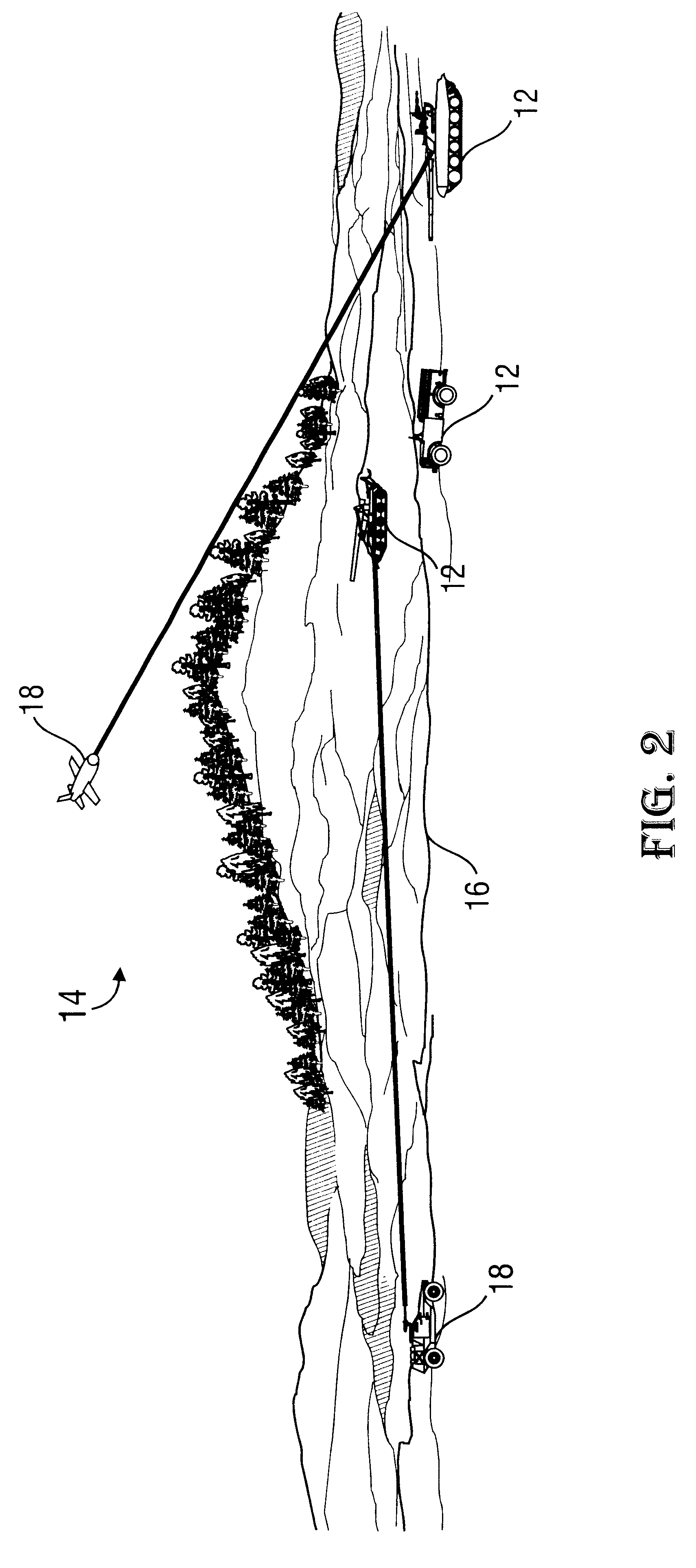
Numerous specific details are set forth below in the detailed description of particular embodiments in order to provide a thorough understanding of the present invention. However, one of ordinary skill in the art having the benefit of this disclosure will understand that the present invention may be practiced without many of the details presented since such details will be necessary or useful depending on the particular embodiment being employed. For instance, the invention is placed in the context of a complete ATR system including data acquisition and object detection to facilitate an understanding of the invention. Conversely, in other instances, well known details have not been described in detail for the sake of clarity so as not to obscure the invention. It will be appreciated that supplying such details would be a routine undertaking for those of ordinary skill in the art, even if a complex and time-consuming task, given the benefit of this disclosure.

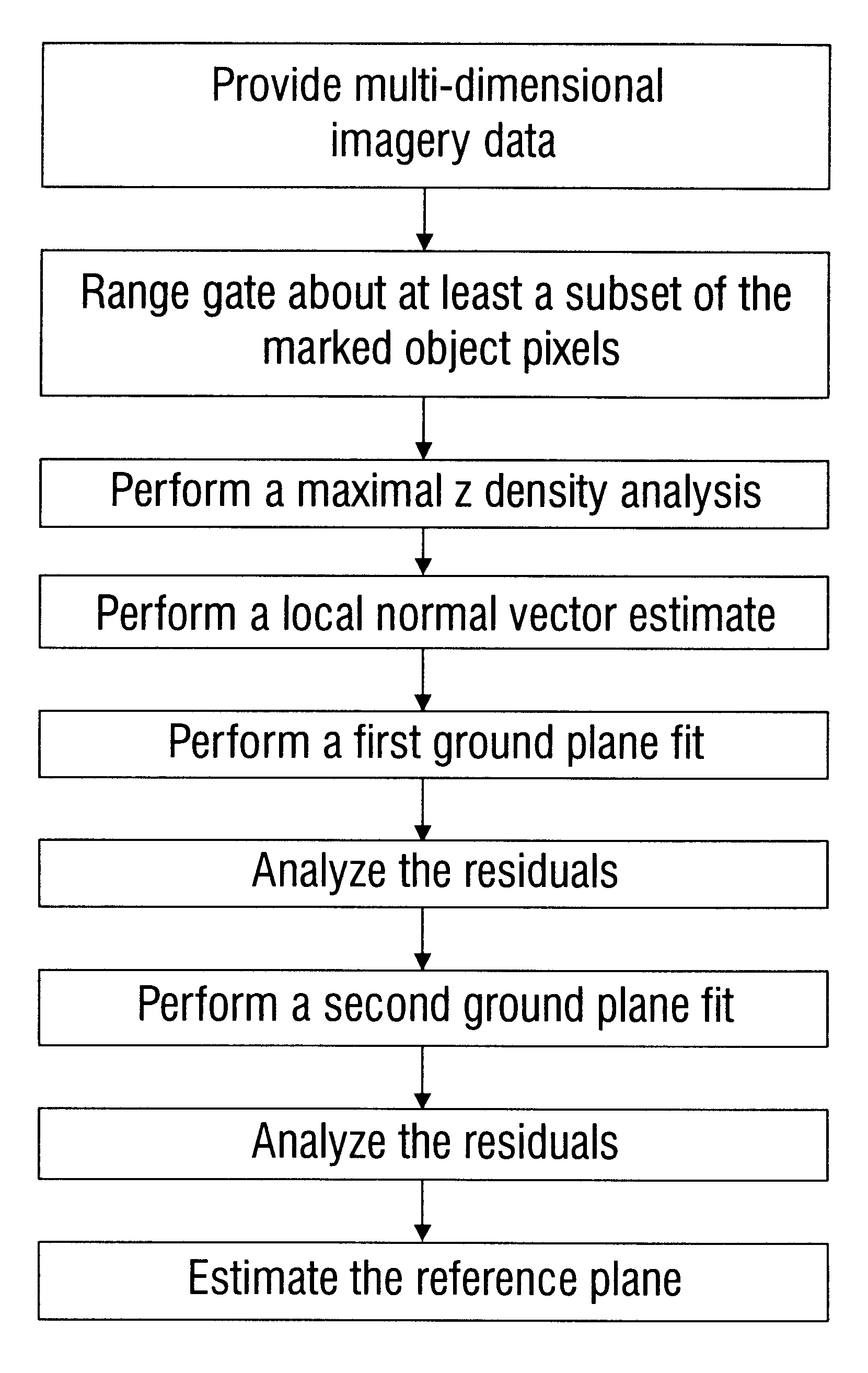
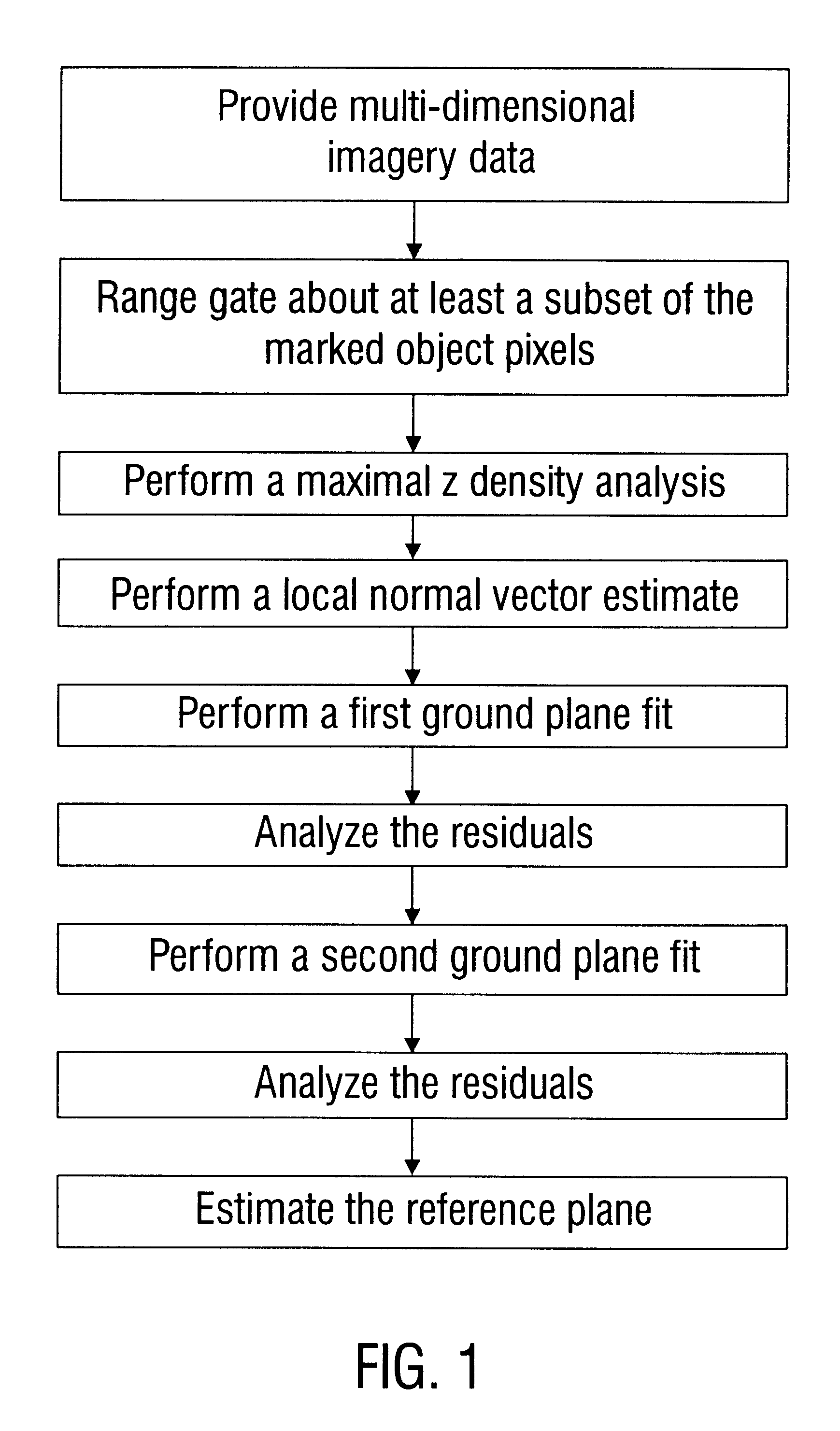
5.1 Illustrative Method ...


PUM


Abstract

A method for determining the reference plane in multi-dimensional data is disclosed. In one embodiment, the method includes (a) providing multi-dimensional imagery data, referred to as set A, including an array of pixels having object pixels marked; (b) range gating about at least a subset of the marked object pixels, including marking pixels outside the range gate to form an unmarked pixel subset of set A, referred to as subset B; (c) performing maximal z density analysis on subset B, including marking pixels outside the maximum density to form an unmarked pixel subset of subset B, referred to as subset C; (d) performing a local normal vector estimate on subset C, including marking pixels having a normal vector exceeding specified threshold L from nominal to form an unmarked pixel subset of subset C, referred to as subset D; (e) performing a first ground plane fit on subset D, each pixel producing residual value X, cumulatively known as residual set X; (f) analyzing residual X, including performing a residual density analysis and marking pixels whose residual value X exceeds specified threshold M to form an unmarked pixel subset of subset D, referred to as subset E; (g) performing a second ground plane fit on subset E, each pixel producing residual value Y, cumulatively known as residual set Y; (h) analyzing residual set Y, including marking pixels whose residual value Y exceeds specified threshold N to form an unmarked pixel subset of subset E, referred to as subset F; and (i) estimating the reference plane for subset F.

Description

1. INTRODUCTION1.1 Field of the InventionThe present invention pertains to identifying objects in multi-dimensional imagery data and, more particularly, estimating the ground plane in multi-dimensional imagery data.2. BACKGROUND OF THE INVENTION2.1 Acquisition of Multi-Dimensional Imagery DataMulti-dimensional imagery data is an electronic picture, i.e., image, of a scene. Multi-dimensional data may be acquired in numerous ways. Laser Detection And Ranging ("LADAR") systems are commonly employed for this purpose. Referring to FIG. 2, laser signals are transmitted from a platform 18 onto a scene, e.g., a scanned field of view. Upon encountering object(s) 12 and surrounding environment 14, varying degrees of the transmitted laser signals, characteristic of the particular scene or portion thereof, are reflected back to and detected by a sensor on the platform 18. The platform 18 can then process the reflected signals to obtain multi-dimensional data regarding the object 12 causing the ...

Claims


Application Information

Patent Timeline
Patent Type & Authority Patents(United States)
IPC IPC(8): G06K9/00G06T5/00G06T17/00
CPCG06T7/0081G06T17/00A63F2300/643G06T2207/10036G06T2207/30212G06T2210/21G06T7/11
Inventor BORNOWSKI, ARTHUR STEVEN
Owner LOCKHEED MARTIN CORP
Why Eureka
Try Eureka