System and method for electronic stabilization for second generation forward looking infrared systems

a forward-looking infrared and electronic stabilization technology, applied in the field of imaging systems, can solve problems such as image jitter, residual servo errors, and high frequency motion of line-of-sight, and achieve the effects of improving image quality, improving image quality, and improving image quality

Inactive Publication Date: 2004-04-13
RAYTHEON CO
View PDF8 Cites 29 Cited by
  • Summary
  • Abstract
  • Description
  • Claims
  • Application Information

AI Technical Summary

Problems solved by technology

Both FLIR and visible imaging systems suffer from image jitter due to vibration.
In general, airborne gimbaled systems are subjected to angular vibration inputs that result in residual servo errors.
If left uncorrected, this error results in high frequency motion of the line-of-sight and degradation of the image.
Hence, this method is not only limited as a solution, but it is costly and adds weight and size to the sensor, making this approach incompatible with many airborne applications.
However, as with the previous method, this technique also increases sensor cost, w

Method used


Image

  • System and method for electronic stabilization for second generation forward looking infrared systems
  • System and method for electronic stabilization for second generation forward looking infrared systems
  • System and method for electronic stabilization for second generation forward looking infrared systems

Examples


Embodiment Construction

Illustrative embodiments and exemplary applications will now be described with reference to the accompanying drawings to disclose the advantageous teachings of the present invention.

While the present invention is described herein with reference to illustrative embodiments for particular applications, it should be understood that the invention is not limited thereto. Those having ordinary skill in the art and access to the teachings provided herein will recognize additional modifications, applications, and embodiments within the scope thereof and additional fields in which the present invention would be of significant utility.

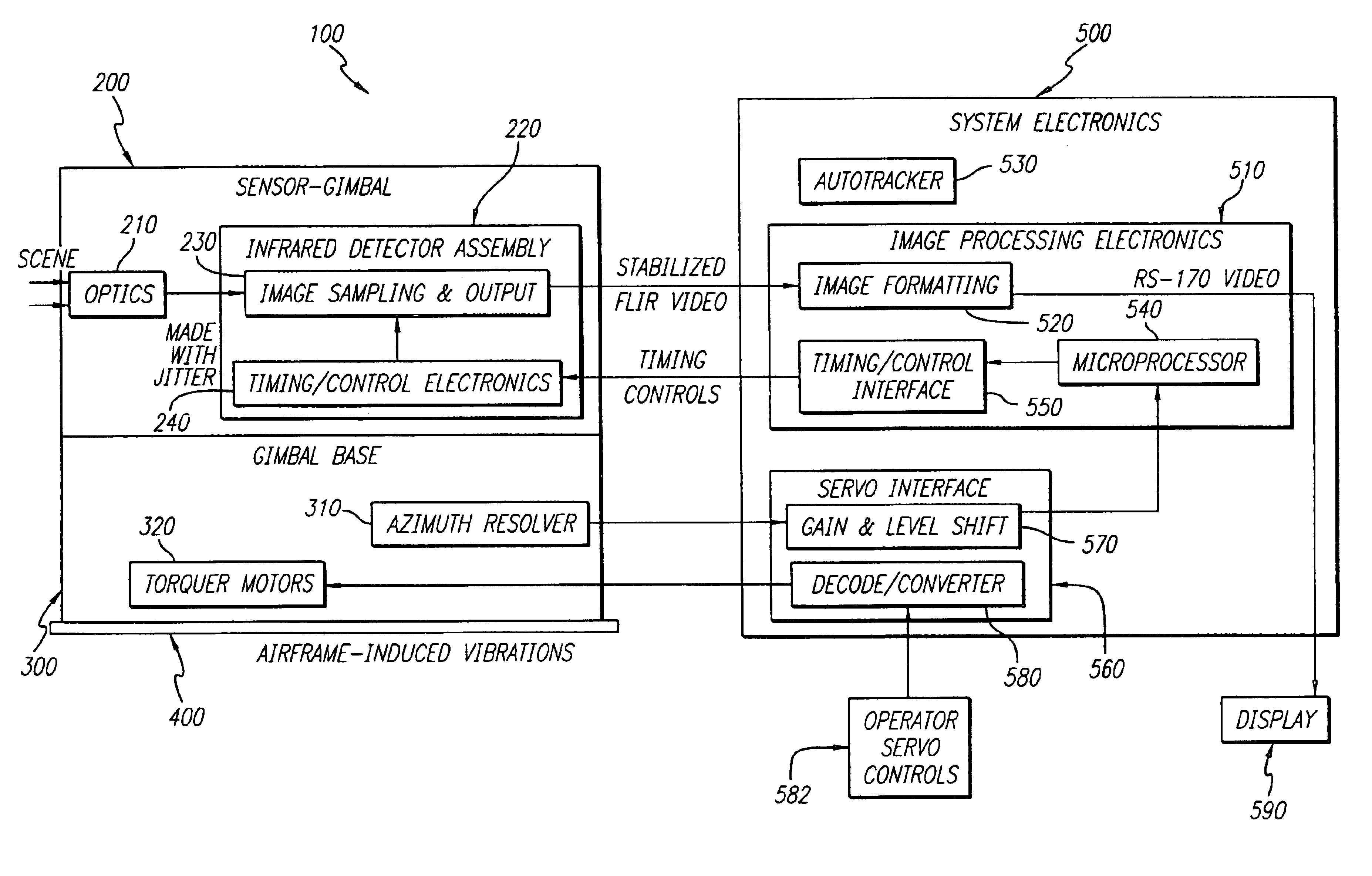
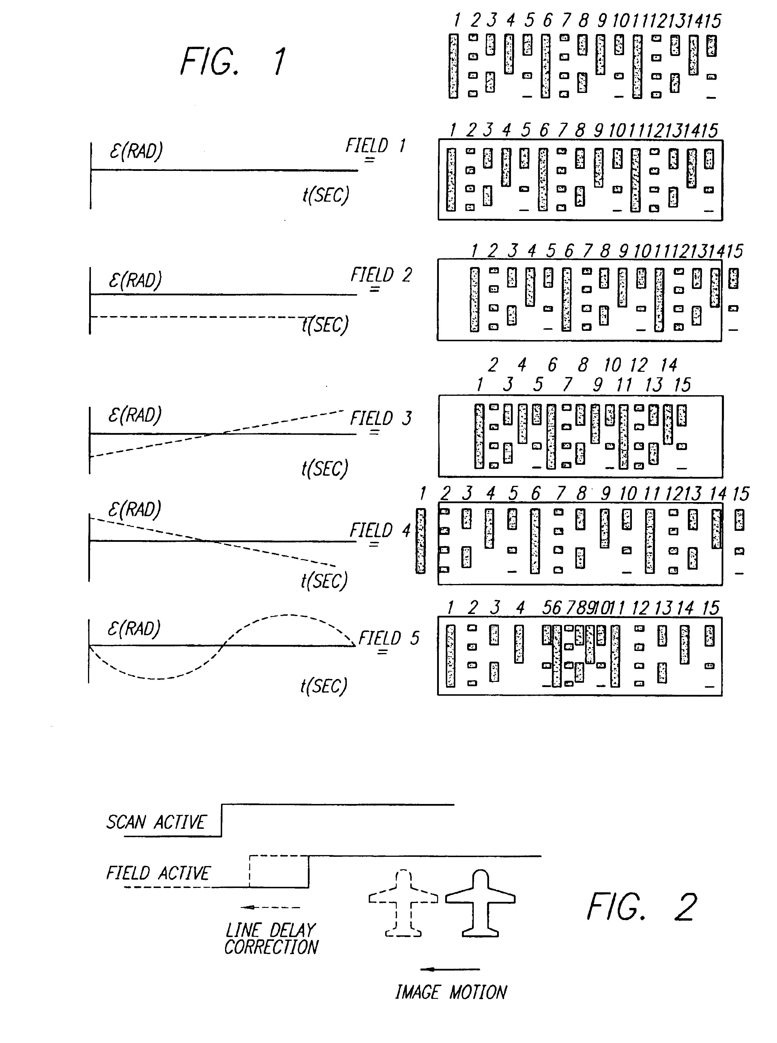
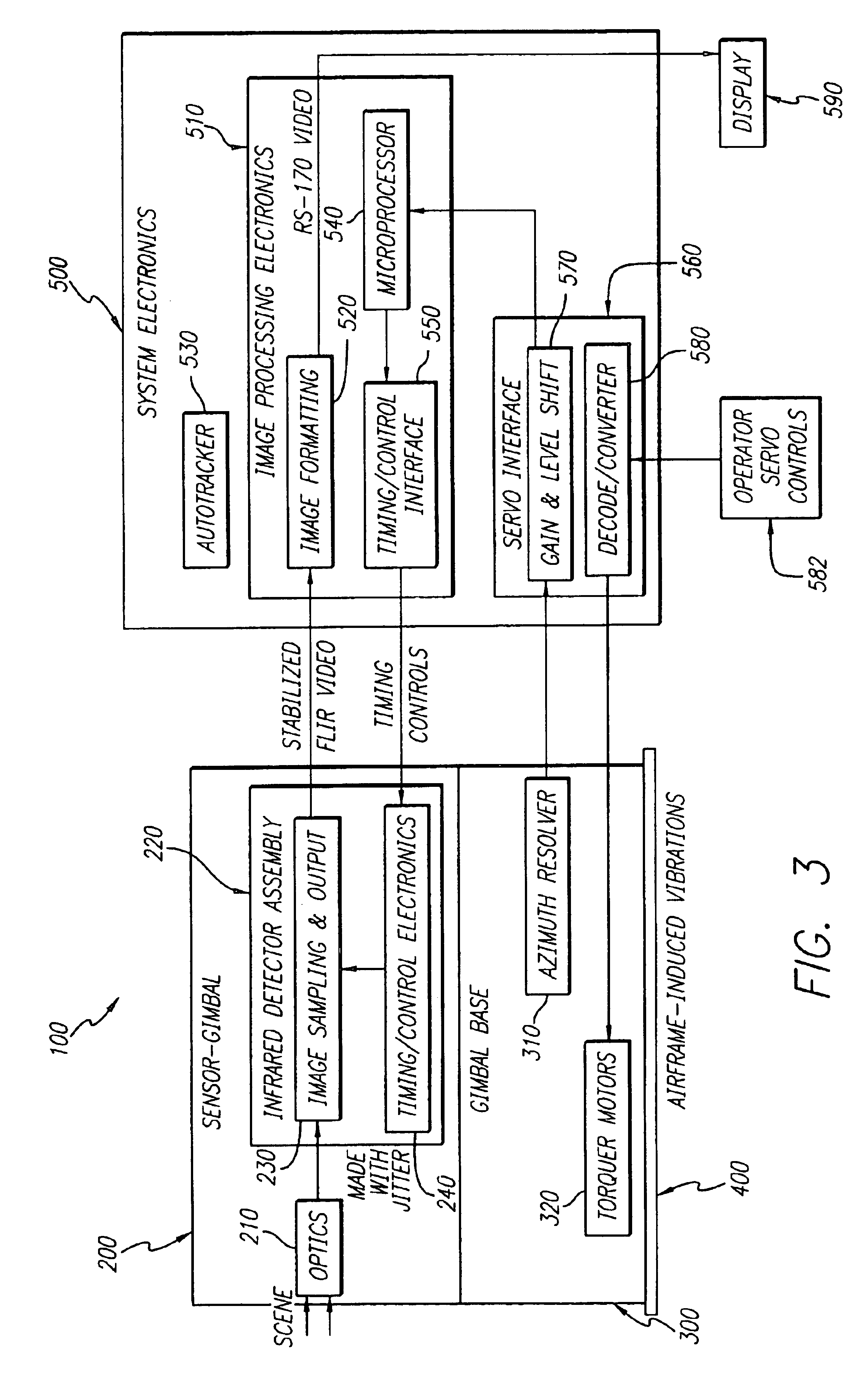
FIG. 1 is a series of diagrams that depict the effects of various servo errors on a scene detected by an illustrative forward-looking infrared imaging system. In general, airborne gimbaled systems are subjected to angular vibration inputs, which result in residual servo errors. This servo error represents the deviation of the gimbal position from the pointing po...


PUM


Abstract

An image stabilization system and method. The inventive system (100) includes an image sampling circuit (230) mounted on a platform (400) for sampling an image in response to timing control signals and outputting a plurality of imaging signals in response thereto. An azimuth resolver (310) detects vibration of the platform and providing a signal in response thereto. A microprocessor (540) adjusts the timing control signals to cause the image sampling circuit (230) to sample the image and thereby compensate for an effect of vibration on the image. In the illustrative embodiment, the microprocessor (540) includes software for compensating for vibration that causes image offset, compressed images, expanded images, and compression and expansion within a single field. The invention provides image stabilization in a purely electronic manner without the need for any moving parts that would typically require control hardware and a significant amount of space. In addition, since LOS motion compensation takes place as the image is being sampled, this method eliminates the need for the large amounts of memory required to store a field of video as well as LOS information for post processing.

Description

1. Field of the InventionThe present invention relates to imaging systems. More specifically, the present invention relates to infrared imaging systems and systems and methods for stabilizing same with respect to vibration.2. Description of the Related ArtImaging systems are widely used for numerous applications from navigation and guidance to astronomy. Infrared imaging systems allow for objects to be detected in low light level conditions that would not otherwise be detectable by the human eye. For this reason, numerous military systems have been supplemented in forward-looking infrared (FLIR) imaging systems.Both FLIR and visible imaging systems suffer from image jitter due to vibration. Previously, imaging systems (particularly FLIR) used mechanical means to maintain the line-of-sight (LOS) stable. A common technique consisted of an inner gimbal, which, in essence, isolated the LOS from platform vibration that normally affected the outer gimbal. In general, airborne gimbaled sys...

Claims


Application Information

Patent Timeline
IPC IPC(8): F41G3/16F41G3/22F41G3/00
CPCF41G3/165F41G3/22
Inventor GROTTODDEN, NICOLE C.BURITICA, GEORGE M.NISHIKUBO, SAM S.
Owner RAYTHEON CO
Why Eureka
Try Eureka