Endface gap sealing of steam turbine packing seal segments and retrofitting thereof

a technology of endface gap and sealing segment, which is applied in the direction of machines/engines, liquid fuel engines, lighting and heating apparatus, etc., can solve the problems of segment endface binding in assembly, affecting overall machine performance, and not being able to maintain zero clearance between segments, so as to improve overall machine performance and reduce steam leakage paths

Inactive Publication Date: 2004-04-20
GENERAL ELECTRIC CO
View PDF12 Cites 27 Cited by
  • Summary
  • Abstract
  • Description
  • Claims
  • Application Information

AI Technical Summary

Benefits of technology

A particular advantage of the present invention resides in the ability to retrofit the spline seals to existing steam turbines as a means of improving overall machine performance. To accomplish this, and during a normal outage for maintenance, the upper outer casing of the turbine is removed and the existing seal segments are rolled from the turbine casing. Slots are machined in the endfaces to receive the spline seals. The segments are then rolled back into the upper and lower outer casings with the spline seals inserted between opposing endfaces, thereby reducing steam leakage paths in existing steam turbines after the retrofit.
In a preferred embodiment according to the present invention, there is provided a steam turbine comprising a rotor having a steam turbine section, a stationary casing surrounding the rotor including the steam turbine section, the casing carrying a plurality of circumferentially extending packing seal segments about the casing at a seal location axially spaced from the turbine section for sealing between the casing and the rotor, each of the segments having endfaces respectively in circumferential registry with opposed endfaces of circumferentially adjacent segments, the endfaces including slots opening circumferentially and in general circumferential registration with one another and a spline seal extending between each of the opposed endfaces of circumferentially adjacent segments and in the slots for minimizing or precluding steam leakage past the registering endfaces.
In a further preferred embodiment according to the present invention, there is provided a steam turbine comprising a rotor having a steam turbine section, a stationary casing surrounding the rotor including the steam turbine section, the casing having a circumferentially extending dovetail-shaped groove carrying a plurality of circumferentially extending packing seal segments about the casing in the groove, the segments carrying labyrinth seal teeth for sealing about the rotor, each of the segments having endfaces respectively in circumferential registry with opposed endfaces of circumferentially adjacent segments, the endfaces including slots opening circumferentially and generally in circumferential registration with one another and a spline seal extending between each of the opposed endfaces of circumferentially adjacent segments and in the slots for minimizing or precluding steam leakage past the registering endfaces.
In a further preferred embodiment according to the present invention, there is provided in a turbine having a rotor, a stationary casing surrounding the rotor and a plurality of circumferentially extending packing ring segments in circumferentially extending grooves about the casing for sealing between the casing and the rotor, a method of retrofitting the packing ring segments to provide seals between the opposed endfaces of adjacent packing ring segments comprising the steps of removing the packing ring segments from the turbine, forming at least one slot in each endface of the removed packing ring segments, disposing a spline seal in slots of opposed endfaces of the packing ring segments and inserting the packing ring segments into the grooves of the casing whereby the spline seals extend between adjacent segments for minimizing or precluding steam leakage flows between the adjacent segments.

Problems solved by technology

The endfaces of the sealing segments are not sealed to one another and the resulting steam leakage flows detrimentally impact overall machine performance.
Further, it is not possible to maintain zero clearance between the segment endfaces for a number of reasons, including manufacturing tolerances which dictate a gap to accommodate the tolerance range.
Additionally, machine thermal transients may cause the segments to bind in assembly, even if designed line to line.
Further, if the casing surrounding the rotor goes out of round, the gaps may become large in one location versus another location.
Still further, if the casing grows thermally more than the packing segments, then the end gaps may increase in dimension relative to the cold condition of the turbine.
Steam leakage flows between endfaces of packing seal segments have therefore become a significant problem, and, accordingly, there is a need for minimizing leakage paths for steam past the endfaces of circumferential packing seal segments in a steam turbine.

Method used


Image

  • Endface gap sealing of steam turbine packing seal segments and retrofitting thereof
  • Endface gap sealing of steam turbine packing seal segments and retrofitting thereof
  • Endface gap sealing of steam turbine packing seal segments and retrofitting thereof

Examples


Embodiment Construction

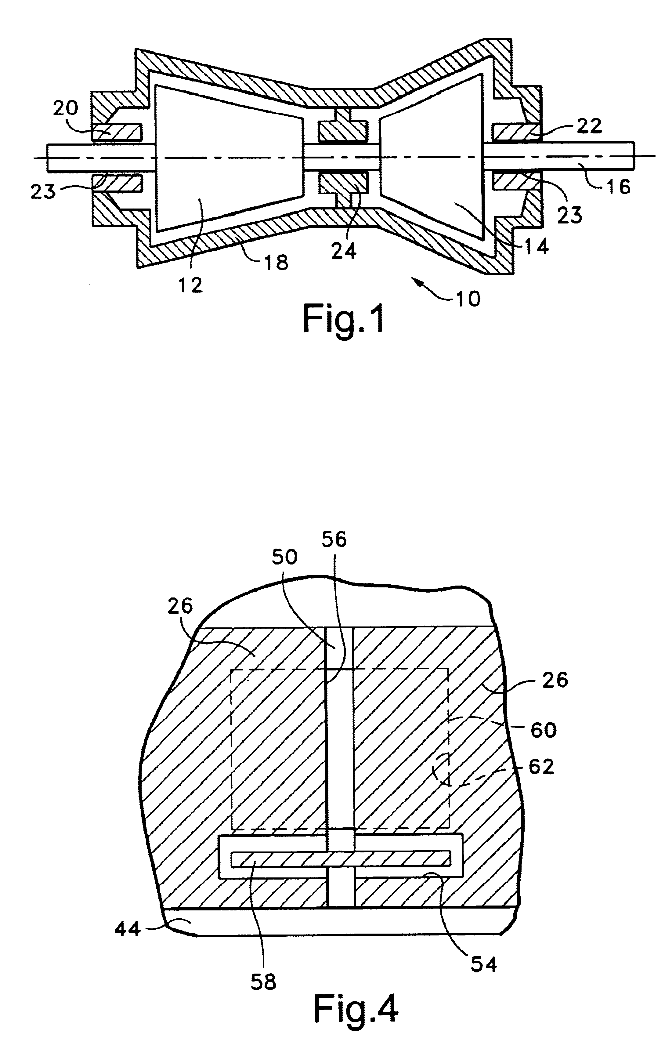
Referring now to the drawings, particularly to FIG. 1, there is illustrated a steam turbine, generally designated 10, and in this example comprised of a high pressure turbine section 12 and an intermediate pressure turbine section 14 mounted on a single integral rotor 16 extending beyond opposite ends of the steam turbine casing 18. It will be appreciated that the rotor 16 is driven in rotation by the high and intermediate pressure turbine sections 12 and 14, while the casing 18 remains stationary. Circumferentially extending packing seal segments are located in the stationary casing 18 at opposite ends 20 and 22 of casing 18, i.e., at locations 23 spaced axially from the turbine sections 12 and 14. In the illustrated turbine having high and intermediate turbine pressure sections, additional circumferentially extending packing ring segments are disposed about the shaft 16 intermediate the high and intermediate pressure sections 12 and 14, respectively, of the turbine at 24. It will ...


PUM

PropertyMeasurementUnit
circumferential dimensionaaaaaaaaaa
circumferential distanceaaaaaaaaaa
pressureaaaaaaaaaa

Abstract

Spline seals are disposed in circumferentially registering slots of adjacent arcuate sealing segments disposed in grooves of the casing of a steam turbine about a rotor. The spline seals extend in the gap between the endfaces of the segments and minimize or preclude steam leakage past the endfaces. The spline seals may be oriented axially or inclined radially to minimize leakage paths in the radial inclined and axial directions, respectively. The spline seals are disposed in the slots which may be formed as part of original equipment manufacture or may be machined in segments with the spline seals provided as retrofits.

Description

BACKGROUND OF THE INVENTIONThe present invention relates generally to seals between circumferentially registering endfaces of packing seal segments in a steam turbine and particularly relates to spline seals between endfaces of packing seal segments circumferentially disposed end-to-end in a stationary packing casing of the steam turbine and methods of retrofitting the spline seals.In a steam turbine, there are circumferentially extending packing seal segments disposed in the packing or stationary casing at opposite ends of the turbine and in sealing relation with the rotor. In certain steam turbines, the packing seal segments are provided intermediate pressure opposite ends of the rotor between high and intermediate turbine sections. These packing seal segments minimize or preclude steam leakage from the rotor ends or through leakage paths between the high and intermediate pressure sections of the steam turbine within the stationary casing. It will be appreciated that the sealing s...

Claims


Application Information

Patent Timeline
Patent Type & Authority Patents(United States)
IPC IPC(8): F01D11/00F01D11/02F16J15/08F16J15/12F01D25/00F16J15/447
CPCF01D11/003F01D11/005F01D11/02F16J15/0812F16J15/122F16J15/0887Y10T29/49721Y10T29/49318Y10T29/49716Y10T29/49719
Inventor BURDGICK, STEVEN SEBASTIAN
Owner GENERAL ELECTRIC CO
Why Eureka
Try Eureka