Apparatus for measuring the bioelectrical impedance of a living body

a technology of living body and apparatus, applied in the field of apparatus for measuring the bioelectrical impedance of living body, can solve the problems of inability to meet the needs of patients,

Inactive Publication Date: 2004-04-20
TANITA CORP
View PDF4 Cites 47 Cited by
  • Summary
  • Abstract
  • Description
  • Claims
  • Application Information

AI Technical Summary

Benefits of technology

With the arrangements described above the electric current flowing just ahead of one or the other selected point of the living body can be measured, thereby eliminating any errors which otherwise, would be caused by the stray capacitances of the cables. Positioning the high-input impedance buffer circuit close to the voltage determining electrode and making an electric connection thereto effectively minimizes the passage to the infinitely high-impedance input for voltage-representative signals to follow, accordingly reducing the adverse effect caused on the way by the surrounding disturbance or noise signals. The flowing of the impedance-representative currents into the impedance gauge via the impedance-matched, shielded-conductor cables effectively minimizes the adverse effect caused by the surrounding disturbance or noise signals. Finally, use of cables of equal length in which the impedance-representative currents flow makes their transmission time equal, so that the signal delays may be cancelled to eliminate such a phase lag as would be caused if the cables of different lengths were used.

Problems solved by technology

These stray capacitances will have an adverse effect on the measurement.
The current I1 flowing from the impedance gauge into the high-frequency current supplying cable C1 (measured by the current detector) cannot be equal to the current I3 passing through the impedance Z, thus causing an error in measurement.
Such an error can be corrected to some extent, but no satisfactory correction can be made; as the cables change in position, their stray capacitances vary.
Thus, the measurement will be adversely affected, and the adverse effect is apt to increase with the increase both of the frequency of the electric current and of the cable length.
It takes a significant time for the current signal I1 to flow from one terminal N1 to the other terminal N2 through the out-going high-frequency current supplying cable C1, the load Z and the in-coming high-frequency current supplying cable C2, allowing this delay time to appear as phase lag, which is proportional to the frequency of the electric current flowing in the load Z, thus contributing to the error in the measurement.

Method used


Image

  • Apparatus for measuring the bioelectrical impedance of a living body
  • Apparatus for measuring the bioelectrical impedance of a living body
  • Apparatus for measuring the bioelectrical impedance of a living body

Examples


Embodiment Construction

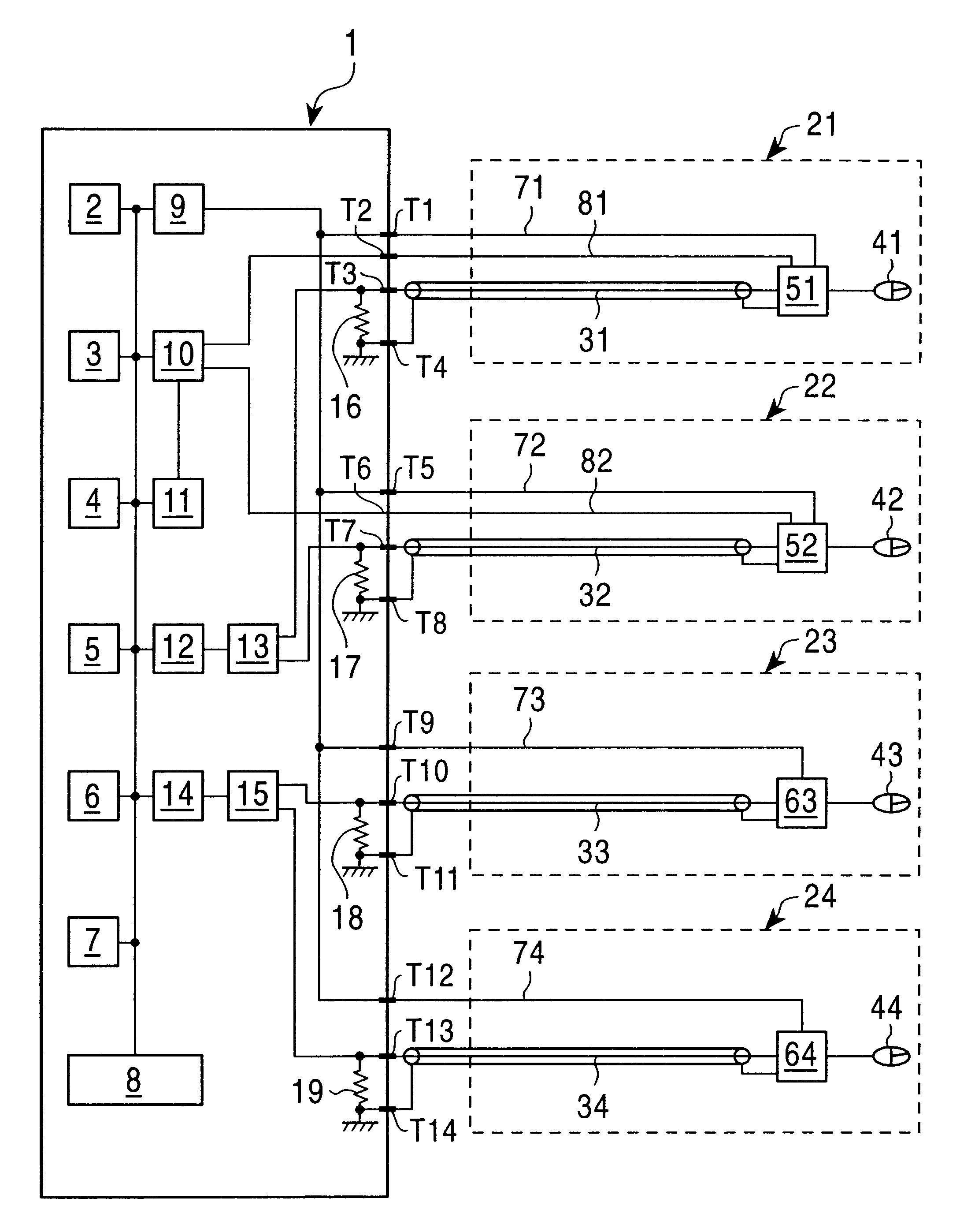
Referring to FIG. 1, a bioelectrical impedance gauge according to the first embodiment (the so measured bioelectrical impedance being used in analyzing and assessing some components of the living body) comprises mainly a gauge center 1, a pair of high-frequency current supplying probes 21, 22 for supplying two points selected in a living body with a high-frequency current, and a pair of voltage measuring probes 23, 24 for measuring the voltage appearing between another two points selected in the current passage in which the high-frequency current.

The gauge center 1 includes a control-and-arithmetic operation processing unit 8 for controlling the whole operation of the bioelectrical impedance gauge and for processing the arithmetic operation on measured data, a ROM 2 connected to the control-and-processor 8 for storing the controlling and processing software programs, a RAM 3 for storing the data provided by measurement and the software program for arithmetic operation, an auxiliary ...


PUM


Abstract

Disclosed is an improved bioelectrical impedance gauge which is so designed that the high-frequency current flowing between two selected points in a living body may be detected in the vicinity of either selected point, and that the voltage appearing between two points selected in the current passage in which the high-frequency current flows may be applied to a high-impedance buffer circuit proximate to the two points selected in the current passage.

Description

1. Field of the InventionThe present invention relates to an apparatus for measuring the bioelectrical impedance of a living body in which the bioelectrical impedance can be determined by making a weak current of high-frequency flow from one to the other selected point in the living body, and by determining the weak current of high-frequency flowing through the current passage between the opposite selected points and the voltage appearing between another two selected points in the current passage in which the weak current flows.2. Prior ArtComposition assessment of a selected portion of a living body in terms of its bioelectrical impedance is known from the magazine, "The American Journal of Clinical Nutrition", 41(4)810-817 1985, "Assessment of fat-free mass using bioelectrical impedance measurement of the human body". Also, an apparatus for analyzing the composition in a selected portion of a living body in terms of the bioelectrical impedance appearing in the selected portion is ...

Claims


Application Information

Patent Timeline
Patent Type & Authority Patents(United States)
IPC IPC(8): A61B5/05A61B5/053
CPCA61B5/05A61B5/053
Inventor FUKUDA, YOSHINORI
Owner TANITA CORP
Why Eureka
Try Eureka